
Tecnología e Innovación
Ciencia y Poder Aéreo ISSN 1909-7050 / E-ISSN 2389-946 / Volumen 15 (1) enero-junio del 2020 / Colombia/ pp. 108-134 Doi: https://doi.org/10.18667/cienciaypoderaereo.519
Fecha de recibido: 25 de enero del 2020 | Fecha de aprobación: 29 de abril del 2020
German Wedge Rodríguez Pirateque
Magíster en Ingeniería Mecatrónica
Nelson Arzola de la Peña
Doctor en Ciencias Técnicas
Ernesto David Cortés García
Ingeniero Mecatrónico
* Artículo de investigación derivado del proyecto Desarrollo de arquitecturas de control en sistemas multiagente para servicios de observación terrestre. Financiado por la Universidad Nacional de Colombia.
This article is intended to contribute to the development of proprietary technologies and the evaluation and selection of integrated technologies in the study of the aerospace concept necessary for the processes of technological appropriation. The problem addressed lies in the lack of modular platforms and lowcost test systems for experimental development and simulations of satellite systems. Therefore, compare to this the proposal of a scalable modular platform of the 1U CubeSat standard is presented as the main results. The design and characterization process presented from the concept of sustainability, contributes to the use and development of low-cost equipment that minimizes the impact on the environment and, in turn, is practical for its implementation in activities of groups and research centers that promote the diffusion of space technologies in Colombia. The methodology of sustainable design, the definition of design principles and conceptual design, which is materialized with the application of quality function deployment method (QFD), the theory of inventive problem solving (TRIZ), the manufacturability-oriented design (DfM), assemblability (DfA), environmental impact (DfE), reliability (DfR), and safety assessment, are relevant for compliance with the CubeSat operating standards described in CDS. Finally, several constructive modes of the low cost test platforms are proposed with different materials such as 3D prototyping in paper, ABS, MDF wood and aluminum. All of them are small-scale satellite structures designed and constructed at low-cost. These designs result in the materialization to test on-board systems and integration resistance in assembly and materials, in laboratories as vibration test-bench, for research groups or companies interested in promoting the development of space technologies.
Keywords: Modular Platform; Conceptual Design; Sustainable Design; CubeSat; Nanosatellite; Design by Factors; Testbed.
Este artículo busca contribuir al desarrollo de tecnologías propias y la evaluación y selección de tecnologías integradas para los procesos de apropiación tecnológica en el ámbito aeroespacial. El problema abordado surge de la falta de plataformas modulares y de sistemas de prueba de bajo costo que permitan el desarrollo experimental de sistemas satelitales y la realización de simulaciones. Por lo tanto, se presenta la propuesta de una plataforma modular escalable del estándar 1U CubeSat como principal resultado. El proceso de diseño de esta plataforma con criterios de sostenibilidad contribuye al desarrollo de equipos de bajo costo que minimizan su impacto ambiental y son de fácil adopción por parte de grupos y centros de investigación interesados en la difusión de tecnologías espaciales en Colombia. La metodología de diseño sostenible, la definición de los principios de diseño y del diseño conceptual, materializados con la aplicación del método de despliegue de la función calidad (QFD), la teoría para resolver problemas de inventiva (TRIZ), el diseño orientado a la fabricación (DfM), la capacidad de ensamblaje (DfA), el impacto ambiental (DfE), la confiabilidad (DfR) y la evaluación de seguridad, son relevantes para el cumplimiento de los estándares operativos requeridos por CubeSat. Por último, se proponen varios modelos para la fabricación de plataformas de prueba con diferentes materiales, tales como prototipos 3D en papel, ABS, madera MDF y aluminio. Todos estos son estructuras satelitales a pequeña escala diseñadas y construidas a bajo costo. Los diseños propuestos permiten poner a prueba los sistemas a bordo y la resistencia de la integración de ensamblaje y materiales a escala laboratorio, con el fin de que los grupos de investigación o las empresas interesadas promuevan el desarrollo de este tipo de tecnologías espaciales.
Palabras clave: Plataforma modular; diseño conceptual; diseño sostenible; CubeSat; nanosatélite; diseño por factores; banco de pruebas.
Este artigo busca contribuir para o desenvolví mentó de tecnologías próprias e a avaliação e selegao de tecnologías integradas necessárías para os processos de apropriação tecnológica no campo aeroespacial. O problema abordado surge da falta de plataformas modulares e sistemas de teste de baíxo custo permitindo o desenvolvimiento experíencíal de sistemas de satélites e a realização de simulações. Portanto, a proposta de urna plataforma modular eescalável do padrão 1U CubeSaté apresentada como resultado final. O processo de desenho desta plataforma, sob critérios sustentáveis, contribuí para o desenvolví mentó de equipamientos de baíxo custo que mimmizam seu impacto ambiental e podem ser fácilmente adquiridos por grupos e centros de pesquisa interessados na disseminação de tecnologías espaciáis na Colômbia. A metodología de design sustentável, a definição dos principios de design e o design conceitual, materializados com a aplicação do método Desdobramento da Função Qualidade (QFD), a Teoría da Solução Inventiva de Problemas (TRIZ), o Design para Fabricaçao (DFM), a Capacidade de Montagem (DFA), o Impacto Ambiental (DFE), a confiabilidade e a avaliagao da seguranga são relevantes para atender aos padroes exigidos pelo CubeSat. Por último, varios modelos sao propostos para a fabricagao de plataformas de testes com diferentes materiais como prototipos 3D em papel, ABS, madeira MDF e aluminio. Todas estas são estruturas de satélite de pequeña escala projetadas e construidas com materiais de baíxo custo. Os desenhos propostos permitem testar os sistemas a bordo e a resistência da integração de montagens e materiais em escala laboratorial, para que o desenvolví mentó desse tipo de tecnología espacial seja divulgado pelos grupos de pesquisa ou empresas interessadas.
Palavras-chave: Plataforma modular; Design conceitual; Design sustentável; CubeSat; Nanossatélites; Desenho porfatores; Banco de ensaio.
The opportunities that come with the democratization of space open doors to developing countries for the use of technologies and the implementation of standards in the provision of aerospace service. Due to the above, it is necessary to engage into processes, procedures and the use of equipment that project the launching of satellite platforms into orbit, such as the CubeSat standard, due to their reduced costs compared to large classic technologies (Paredes, 2010).
Considering these processes of democratization of space, the research problem identified in this work focuses on the deficit of technological capabilities of Colombia within the aerospace field, since the development of such capabilities involves not only public policy processes, but also the search, development and dissemination of the space field, for which the present project proposes mitigation actions. Said actions focus on the search for solutions, such as the identification of tools and the use of physical means, on which progress can be made both in the knowledge of space technologies and in the dissemination and execution of basic activities for the handling of tests, simulations and the general recognition of the variables related to satellite equipment.
In this sense, it is important to identify different types of aerospace technologies or devices with which services are being supplied in orbit, configuration forms in hardware and software (Match, 2016), and other aspects for the support of these services (Báez & Rodriguez, 2010) regarding the possibility of developing production lines, equipment assembly and even test development with user-friendly platforms.
Advances in the development of small-scale satellites are led widely by the United States, as shown in Figure 1.
The origin and tendency of these types of satellites arose from a materialized project with the name of “CubeSat” (CalPoly, 2009), by the Polytechnic University of California (Cal Poly) and Stanford University, since 1999. Table 1 shows shows the classification used according to the satellite mass.
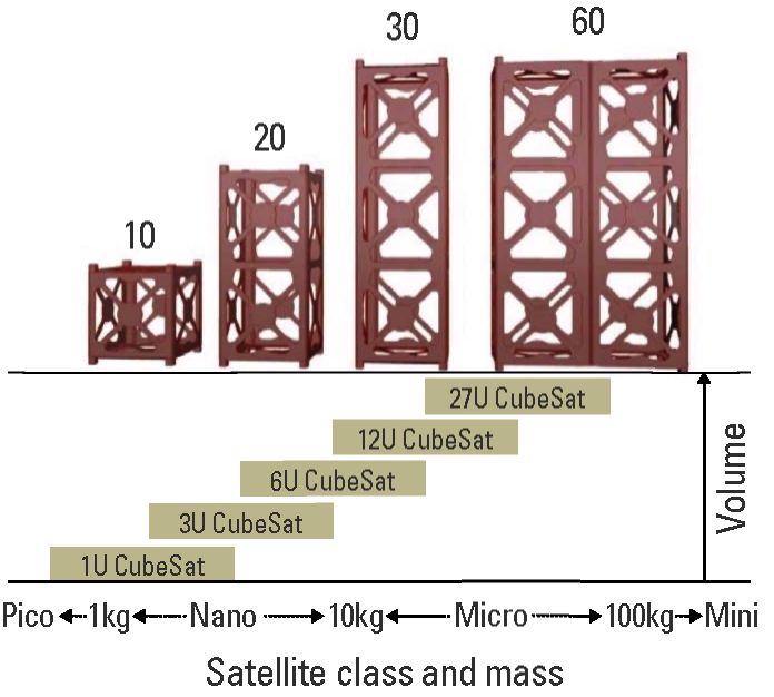
A fundamental purpose of using these smaller satellites is to be able to supply the services of conventional large monolithic satellites using small structures with the same capacities on board, but distributed in different units. Figure 2 shows the use of the standard in dimensional and modular terms, as alternative solutions for ground test systems (Mier-Hicks, 2017).
It also highlights the high demand for the 3U type configuration (Carnahan, 2014) for different mission and use categories (Owen et al, 2013), both on land and in orbit, such as the use of multispectral cameras in one of the developments carried out by Sergio Arboleda University (Diaz-González, 2014). In addition to the use of different types of structures (Medina, 2018), different studies reflect their interest in the search for alternatives and optimal designs for this type of satellites (Camacho, 2016), such as the work carried out in the University of Patras by (Ampatzoglou & Kost, 2018), in others, designs of cubesat with alternative materials (Sandik, 2012), propose methodologies with specific steps for the design of structures (Herrera et at., 2015). Other works from different universities propose designs such as the CPI and CP2 California Polytechnic project, UW CubeSat, Washington, CanX-1, Toronto, Cysat, Lowa, NarcisSat, Stanford, TUSAT1, Tylor, ICE cube, Cornell, AAU CubeSat Aalbort, NCUBE, Norwegian Technique (Romero & Rodriguez, 2005). Others analyze designs with coatings and fixed joints for different types of launchers (Arroyave et al., 2015) or validation of life cycle requirements (Maropoulos & Ceglarek, 2010), which in the end promote the use and development of this type of structure.
Taking this background into account, the design of structural platforms for nano-satellites required in the execution of ground tests is justified by the fact that such platforms can be equipped with the different subsystems and components of the satellite system (Jacobs & Ruiz, 2013) in order to physically demonstrate the affectations or strengths of equipment and dimensionality of the components tested, considering not only their physical characteristics (Gavrilovich et al., 2014) but also the implications of the external environment and the phenomena to which the platforms are exposed at the time of being placed in a specific orbit (Antunes, 2012).
In this sense, the problem addressed in this study lies in the lack of modular platforms and low-cost test systems for the experimental development and simulations of satellite systems. Thus, the design of a CubeSat as a sustainable and materia liza ble product (Ullman, 2010) requires the search for information and possible alternatives for the design of new structures (Araya, 2014) capable of integrating the functionalities of a particular aerospace service (Ulrich, 2015), such as ground observation, which would be the service currently used to address space issues in Colombia and for which the proposals in this article are being formulated. With this, the proposed contribution regarding the design focuses on the utility of replicating satellite structure standards to low-cost modular platforms for laboratory tests and teaching processes in space-related subjects.
This article shows the proposal of scalable modular platform of the 1U CubeSat standard, in addition to the methodology followed for the sustainable development of a nanosatellite. The final scope of the research starts from the design and characterization process of a 1U standard structure, followed by the manufacture of fourtest platforms in different materials, ending with the demonstration of the use of one of these structures in the setup and design of an experimental test on a vibration bench available at the Laboratory of Industrial Electrical Tests of the National University of Colombia (LABE), as one of the many tests that these structures can be subject to.
The structure of this article contains the research procedural route, the development of each of the development phases, the evaluation of each of the stages of the detailed design analysis, and the materialization of the sustainable product design, evidenced in the manufacture of the prototypes real scale using 3D prototyping in paper, ABS, MDF and aluminum, which compiles the proposed innovation intentions for the use of laboratory satellite test equipment. Finally, we present the experimental test on a vibration bench, showing the effects of acceleration and frequency to which these types of structures can be exposed at the time of launching on board rockets to be put into orbit.
Figure 1. Geographical distribution of peak developers and nanosatellites.
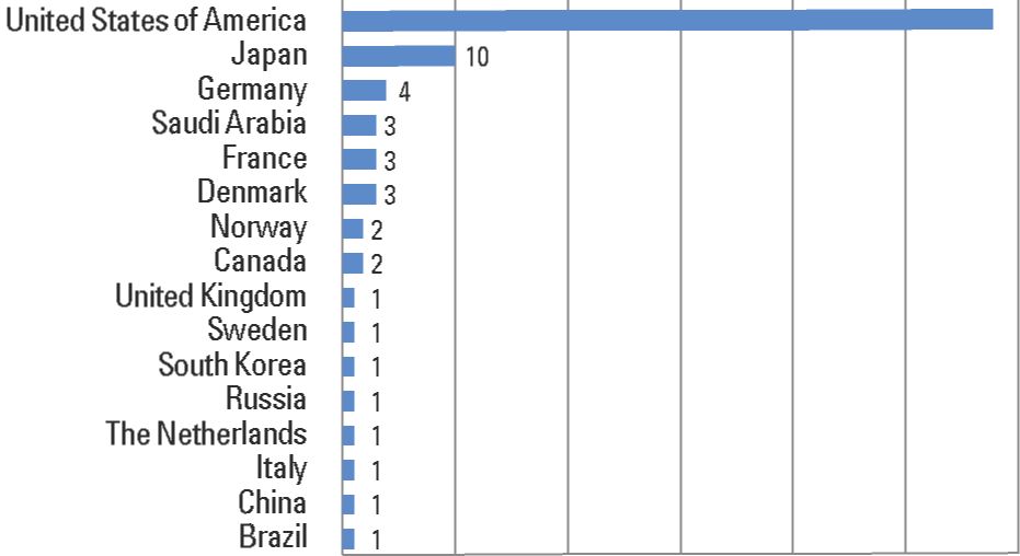
Table 1. Classification of small satellites
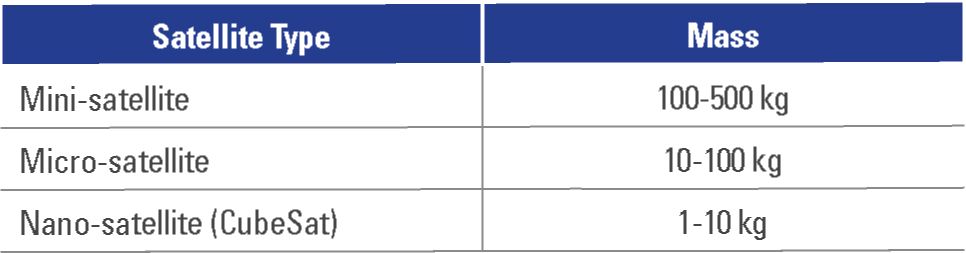
Figure 2. CubeSat basic settings. Source: Poghosyan and Golkar (2016).
Sustainable Design of a Nanosatellite Structure Type CubeSat as a Modular Platform for laboratories, the method was proposed within a descriptive and correlational research methodology through the execution of five structural phases, namely:
a. Definition of design specifications
b. Conceptual design
c. Preliminary design
d. Detail design
e. Application and manufacturing
These phases bring togetherthe levels of analysis and context of the different requirements, standards and applications used for structuring the platform design and the proposal for innovation in laboratory equipment concepts (Herrera-Arroyave & Pérez, 2015) in order to address different specialized areas that gather the application of space-related issues, from academia to the industry and the state (Tirado & Rodriguez, 2016).
The definition of design specifications establishes a series of procedures that allow identify customer needs and translate them into engineering specifications. In this phase, potential competitors were also identified and the main features and attributes of similar competing products were analyzed. Finally, the design problem and sub-problems were established and fully understood.
The conceptual design was approached through the interpretation of the client’s need with its different categories and levels of importance. The analysis of competitors and the description of possible solutions available in the market were developed, not only for satellite laboratory test platforms on a small scale, but also for its components and operating subsystems for putting it into orbit. The functional analysis was also carried out, where the formulation of black and gray boxes of the platform model was obtained, along with the functional decomposition (Ullman, 2010), specified by the generation and integration of the conceptual alternatives of the product.
Throughout the project’s execution, various limitations related to time, material resources, and manufacturing occured. Regarding the time, as a university project, the execution of the prototypes in Paper and ABS considered a term of 6 months. For the aluminum prototype, Aluminum 6061 is poorly accessible in Colombian commerce and its cost tends to be high. Regarding manufacturing, machines such as bending machines and laser cutters were not accessible for financial resources, so designs such as MDF and aluminum were repeatedly changed. Machines such as the CNC milling machine had a limited space to machine the material, so it was necessary to previously manufacture to access the final design. Likewise, the 3D prototyping machines had a delimited internal space, so the dimensions of the designs were changed.
In this sense, and taking as a reference the conceptual design described and previously formulated, several relevant components were then raised for a preliminary and detailed design of the test platform, such as the definition of product architecture, with their respective schemes and interactions at the system level, fundamental for the detailed design to be developed at the end of the proposal.
Subsequently, the detailed design was developed, a phase where the selection of the components, materials and production techniques was made, the functional interfaces were refined, and physical models and useful prototypes were developed to understand the operation of the product, describing the evaluation and compliance of the functions and performance, together with the assessment of manufacturability (DfM), 1 assemblability (DfA)2 (Ullman, 2010), environmental impact (DfE),3 reliability (DfR)4 and safety factors, relevant to compliance with design standards for the CubeSat (Alvarez & Walls, 2016).
Based on these considerations, the design characteristics, manufacturing processes, tooling, improvement strategies, product life cycle analysis, product process tree, assemblability evaluation, testing, and design of experiments were established, with their respective factors. Experimental, variables and analysis results, planned forevaluation of tests on the modular platform were also established (Medina, 2018).
Finally, the production and process parameters were established for product scalability and application of the engineering design techniques available for the management of laboratory test equipment with CubeSat-type platforms, demonstrating the process by manufacturing the full-scale model in 3D printing, to finally verify its modular use in laboratory tests.
Based on the design subproblems deduced from the analysis of different types of structures, customer needs and engineering requirements are defined; this is the basis of the design constitution. The design subproblems identified are the following:
Customer's need was identified after different processes of information analysis and interviews with sector researchers and equipment dealers for launches of nanosatellites, who argue the need for modular platforms capable of providing performance of test systems and portability of functions for the different subsystems of the satellite equipment. This allowed stating the requirement of test benches, as well as the structures to be able to equip and simulate the reference frame of a nano-satellite, in terms of stability control, positioning and responsiveness to level variations in simulated orbit.
Taking as a reference the description of the client’s need and having a possible name for the proposed solution (Nano), Table 2 lists the customer's requirements next to the assigned level of importance, according to a scale between 1 and 5, where 5 means very important.
Based on the functional review, different specific requirements for the platform are added below, as well as its correlation with useful engineering specifications to satisfy the quality function of the basic product design.
Structural Requirements:
Mass requirements and mass distribution:
Technological requirements:
Launching requirements:
Operational requirements:
1) Competition Analysis: The deduction of competitors and suppliers of these platforms results from the debugging and information of contributions to the sector, previously analyzed, and from which the companies ISIS, GOMSPACE, Cubesatkit, Tyvak Nano-Satellite Systems LLC are extracted, as possible references for the outstanding weighting of these requirements, where mainly the levels of forms, unions and requirements of low weight are ratified as the most prominent of the products offered by these companies.
2) Engineering specifications, category and objective values: Engineering specifications are presented indicating for each of them the estimated values and ranges of operation (Table 3), with which it is expected to count in the design of the platform, in the same way the categories and possible magnitudes of being considered for the deployment of the quality function.
In brackets, the score achieved by each of the engineering specifications. This score makes it possible to organize the Engineering Specifications according to their level of importance to meet the expectations of potential customers.
3) Development of the quality function deployment (QFD): The development of the deployment of the quality function addresses the levels of impact and correspondence between the client’s requirements and the engineering specifications raised. In relation to the latter, it is possible to observe not only the correlation of impact between them, but also, as shown in Figure 3, the weights of the most representative specifications, such as the volume of the structure and the capacity of load of the same, for which the different estimation of impact between customer requirements and engineering specifications, account for the design attributes of greater relevance for the product design.
4) Application of the Inventive Problem Solving Technique (TRIZ): As a result of the interactions and results offered by the deployment of the quality function, the two engineering specifications with higher weights were taken as a reference, that is mentioned the volume and load capacity. These engineering specifications represent the contradictions to work according to the TRIZ methodology5 technique appealing. When using this technique (Rodríguez, 2017), the attributes mentioned were related in the characteristics to be improved within the design, since the contradiction effect could generate problems in the characteristics of the row, such as the weight of the moving object and the ease of manufacturing.
These being the most significant characteristics obtained from the quality function, it follows that the most significant inventive principles and that are related to these contradictions are both segmentation and copying and even the fact of being able to replace systems within the design. In this sense, both segmentation and copying refer to the possibility of working with modular systems within the design proposal, which are capable of being integrated and scaled if necessary for the implementation and manufacturing of the platform.
5) Functional analysis: The general status of small-scale satellite technology platforms represents different types of mission, among which we want to highlight related designs for topologies and control of network agents.
Within the most common and generically described satellite architectures, the following subsystems are related:
Additionally, the gray box model is developed as the first outline of the entrances and exits of the system, considering both the gravitational movements of the satellites and the effect of stability and armed with components that the platform must replace. Taking into account the subsystems of the on-board platform for different aerospace service missions (Figure 4), the gray box model is presented, including the processing of the energy, material and information flow conditions for the observation of the states of each of the components and subsystems.
After the deduction of the functional gray box model, the complementary functions (Figure 5) can be approached from the general functions of the system; for example, attitude control (Meissner, 2019), onboard data control, power supply, communications control, propulsion control and, specifically, and as a particular aspect for functional design, the structural control function is resumed. This last main object of study guarantees both the support and well as the protection and maintenance of the equipment on board the platform.
6) Application of creativity techniques and concept generation: The application of creativity techniques in the generation of conceptual solution alternatives for the test platform is supported by external elements such as satellite designs used within the international balltype space station and home artifacts projects for balloon launches, up to design of new models such as the proposed nanosatellite for communications applications and other services. Another generation of concepts is based on the identification of patterns followed by operational models of modular and deployable platforms, which are currently used in the market.
Finally, the generation of concepts is supported by the search for patents of platforms used for multiple purposes, making use of creativity techniques by a na logies focused on the history of patents gra nted in the market.
7) Concept Integration: After the correlation estimates between customer requirements and engineering specifications, added to the functional configuration of the platform, the creation of useful concepts to interrelate the sub-functions of the system is reached through creativity techniques, as is the case presented in Figure 6, with the classification tree. The latter allows the integration of the com ponents of each subfunction and clarifies the guidelines for the conceptualization of component operation.
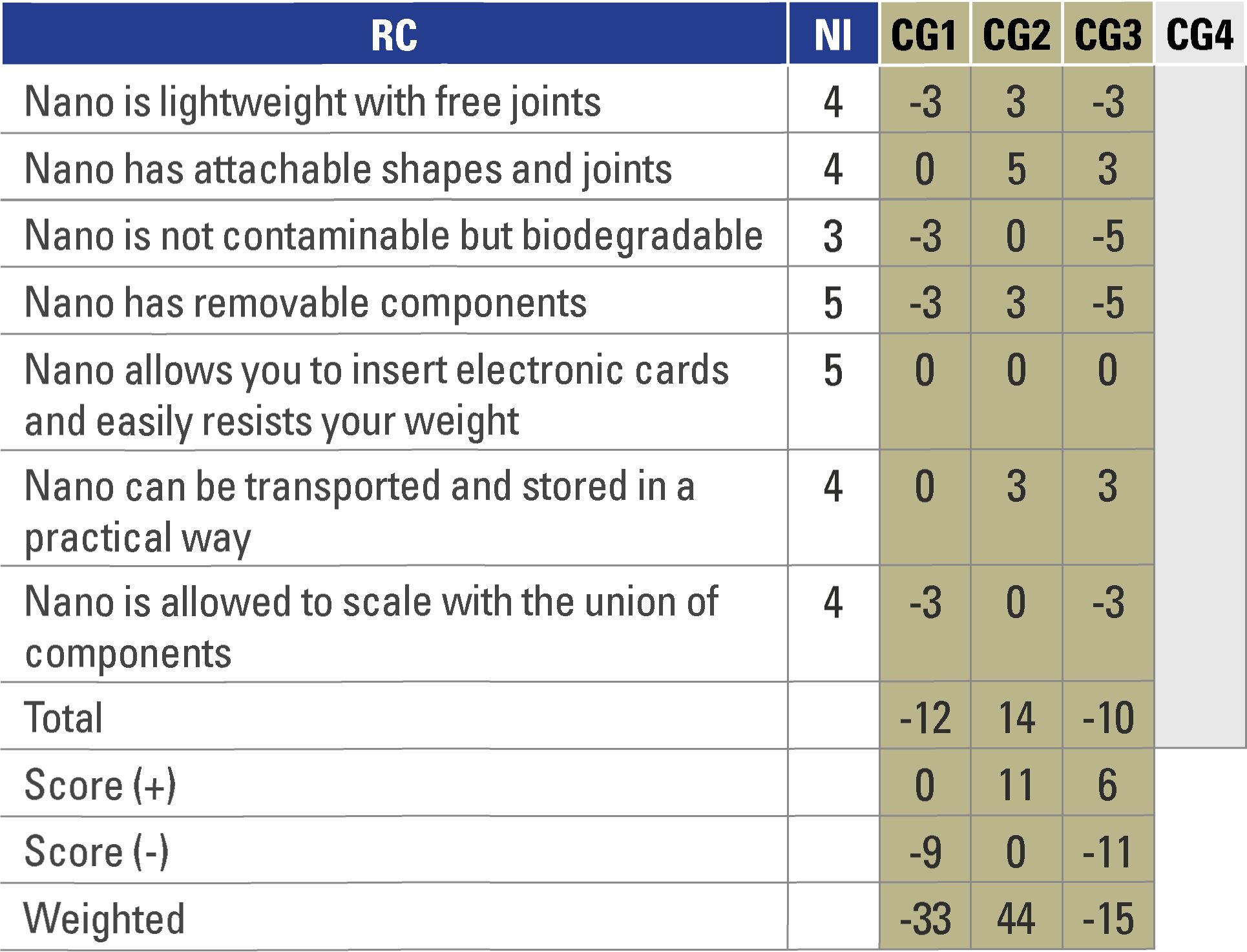
8) Evaluation procedure and concept selection: In general terms and after the process of formulating the possible types of concepts for the design of the test platform, these are consolidated in the Pugh decision matrix, as shown in Table 4. This matrix allows the evaluation of the different global concepts, obtained by means of combination techniques of elements such as bars, rivets, screws, sections, stops and even profiles, considering CG16, CG27, CG38, CG49. As a result of the application of this evaluation technique, the integrated concept number 2 is obtained as the most promising and strong as a design solution.
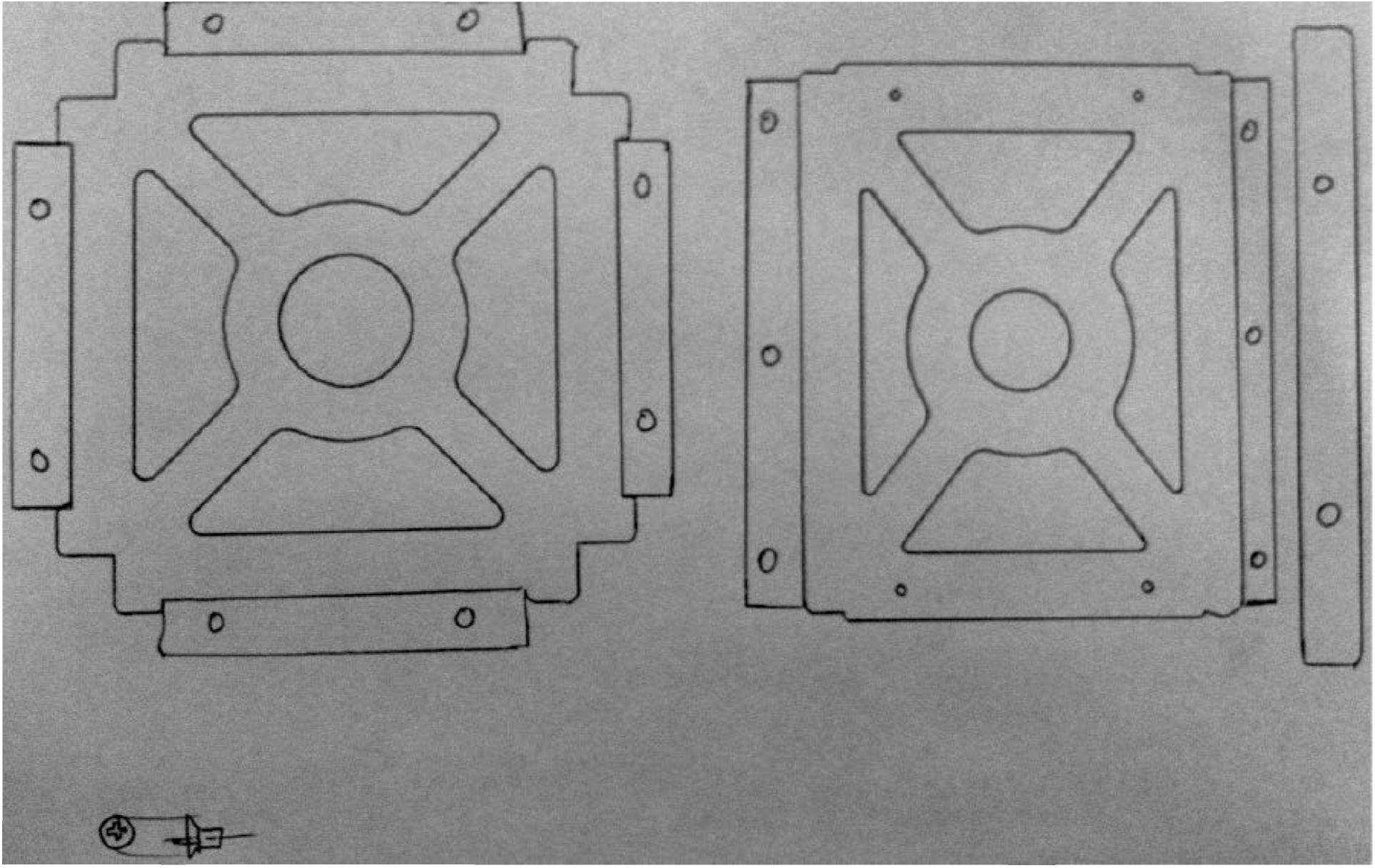
9) Effective transmission of the Global Dominant Concept (CGD): As a result of the conceptual design processes, the previous concepts are proposed as alternatives of use in the conformation of shapes and volumes, which meet both the inventive principles of the TRIZ matrix and the integration of the basic elements of the concepts. The guidelines forthe construction of a model based on the dominant global concept are given, with the combination of side sections bars and screw-type joint elements, as shown in Figure 7.
In general terms, a structure with adjustment of the lateral faces is proposed (Figure 7), which are the sections included in the concept, unlike the plates that were previously proposed without special shapes or holes, thus achieving visualization of the internal components, as well as the provision for air circulation and thermal protection of the components.
Table 2. Levels of importance for customer requirements.
Table 3. Values and ranges of operation.
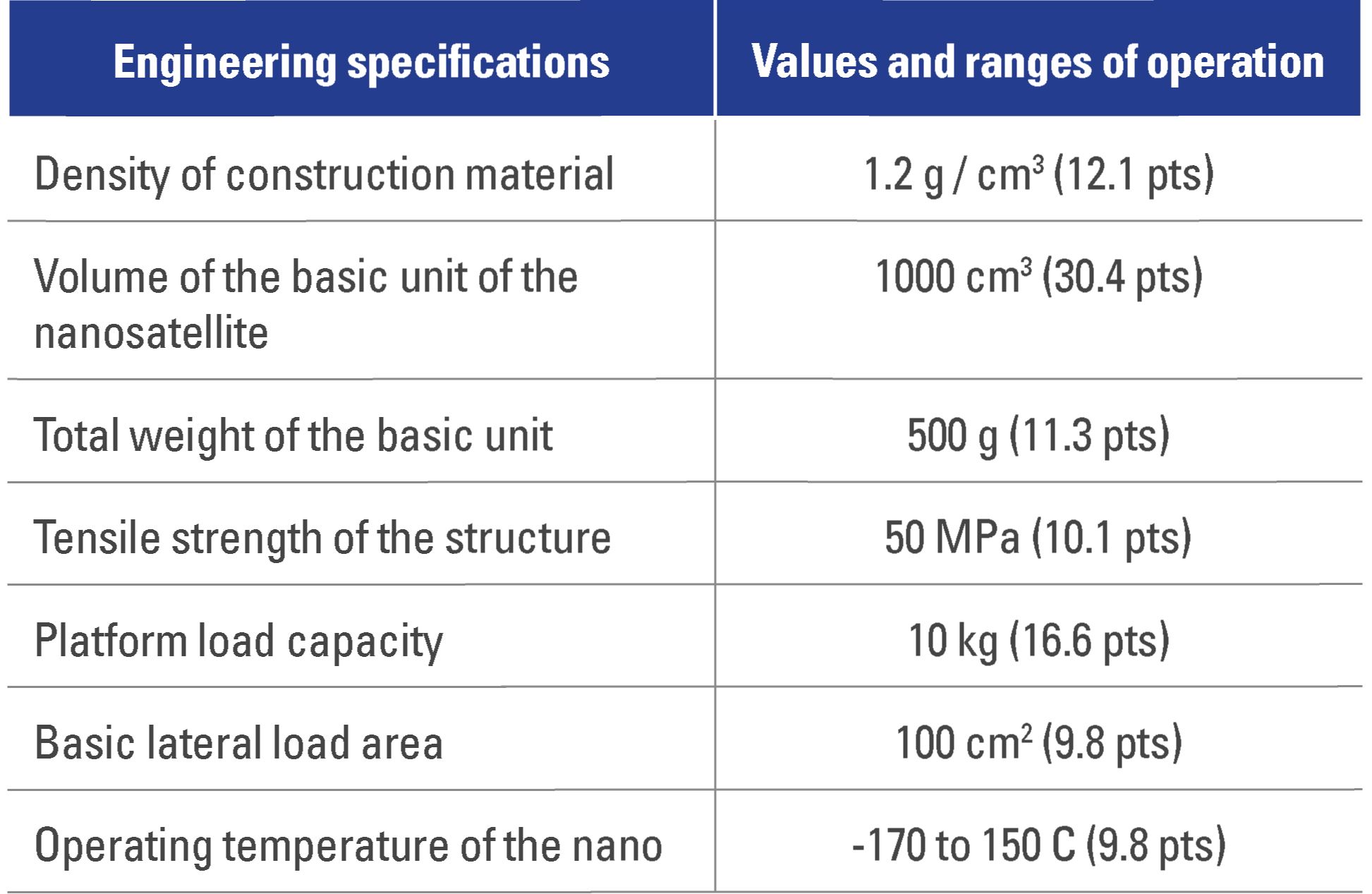
Figure 3. Degree of interaction between customer requirements vs. engineering specifications.
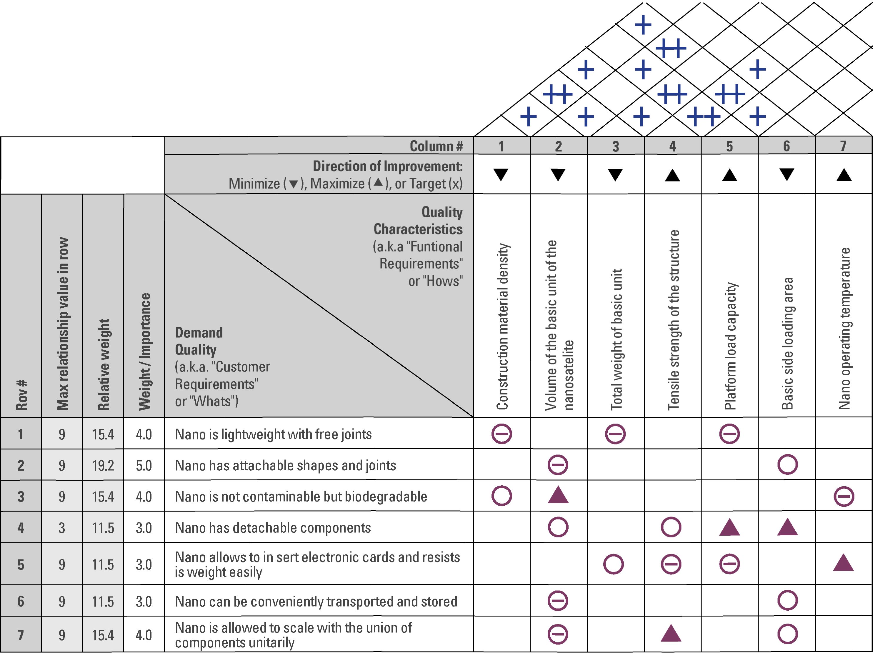
Figure 4. Gray box model for the CubeSat.
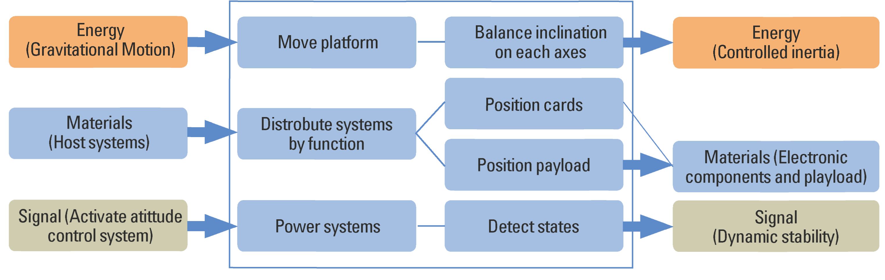
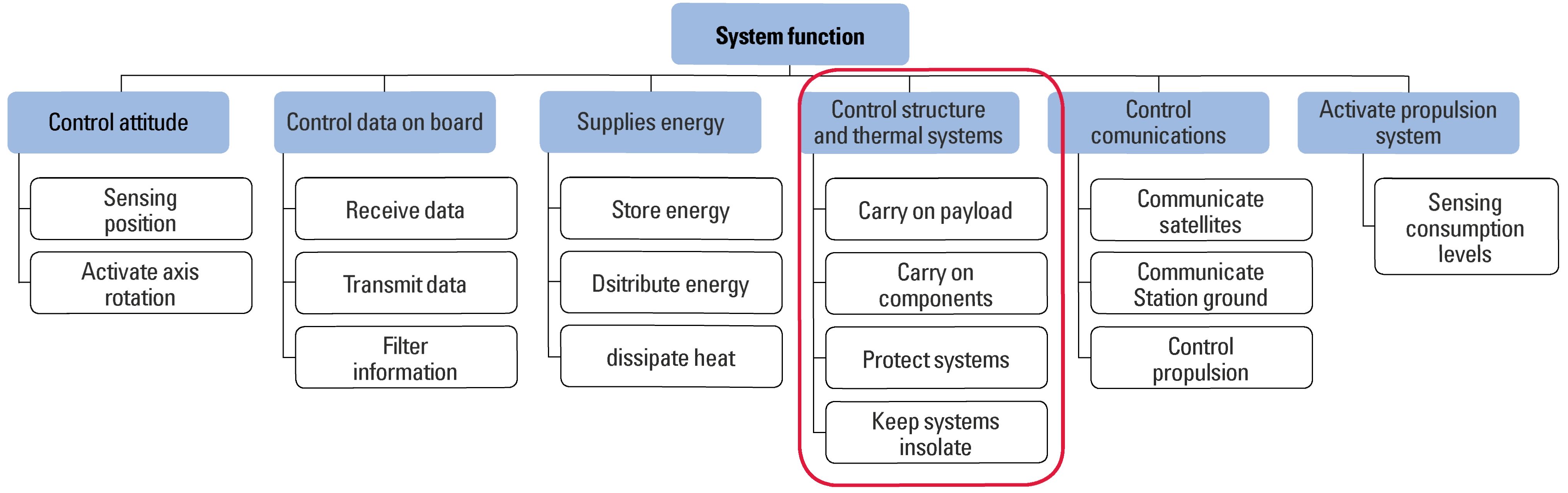
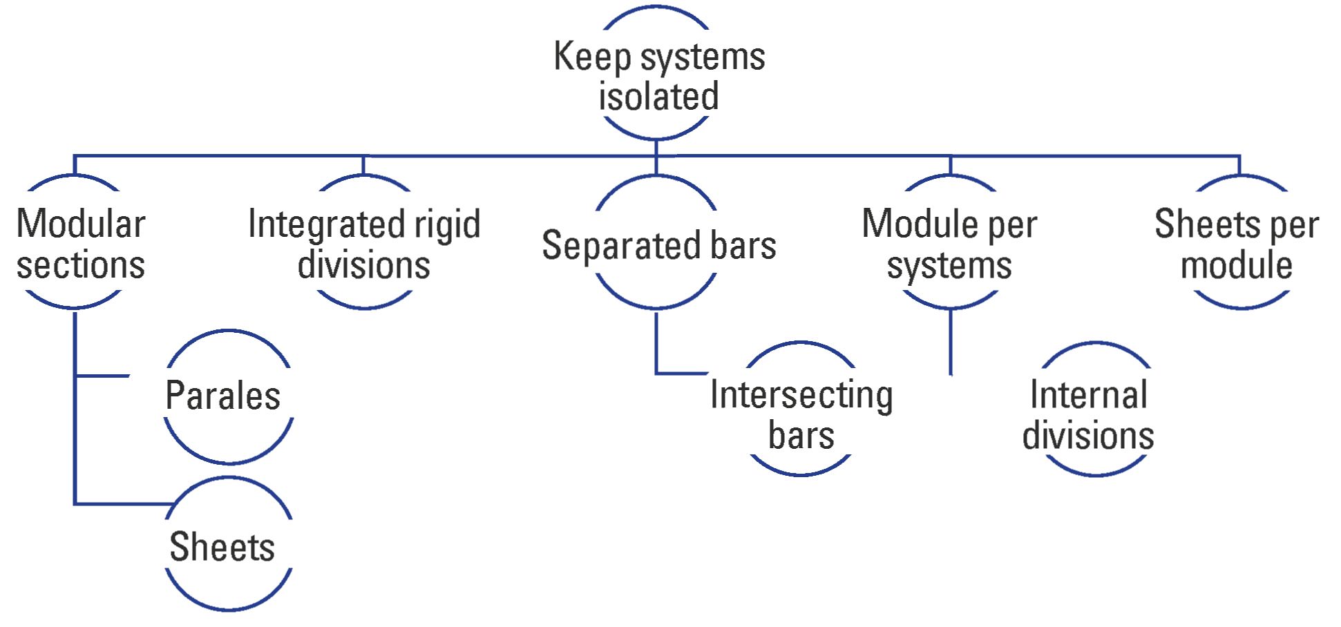
Table 4. Pugh decision matrix for the evaluation of the different concepts for the testing platform.
In reference to the conceptual design developed so far for the advancement in the development of the structural system of a nanosatellite, different aspects prior to the definition of the design at the system level are related, considering the need to properly document the architecture of the product.
1) System level design. Product Architecture Definition: Faced with these characteristics and effects to which the spatial structures are exposed, the different subsystems of the nanosatellite (Herrera-Arroyave & Pérez, 2015) are resumed, and are described below, to emphasize the design approach at the system level related to the structure of the equipment.
i. Structural subsystem (shapes and rigidity - made of aluminum alloys).
ii. Thermal subsystem (active or passive maintains temperature control, its passive category refers to surface finishes and coatings).
iii. Control and attitude determination subsystem (ADCS), measures and guides, position and orientation.
iv. Electrical Power subsystem (EPS) - supplies and guarantees energy in the light and shadow phase.
v. Communications subsystem (sends and receives data from the payload to the ground station, using electromagnetic waves with antennas).
vi. Command and data subsystem (OBC, On Board Computer) is the on-board control computer, with PC-104 standard connector electronic cards, fire resistant and made of glass fiber reinforced polymer (GFRP), Glass Fiber (Reinforced Polymer item, manufactured by Commercial-Off-The-Sh elf-COTS).
On the other hand, in order to advance in the process of detailed design and product generation, it is important to identify the general requirements of space materials, arranged to withstand the difficult conditions to which they are subjected while in orbit:
a. Tempering
b. Tenacity
c. Extreme temperature resistance
d. Abrasion resistance
e. Wear resistance
f. Corrosion resistance
In this sense, and in accordance with the described subsystems, product development focuses on this stage in the evaluation of thestructural subsystem. Taking as a reference both the modular architecture and the geometric arrangement at the system level, different interactions are established between each of the subsystems of the structure in Figure 8, such as the versatility and objective stability between the side sections of the model with the respective support bars, which are subject to vibrations at launch and, subsequently, to dynamic loads by the vertical movement of the loading device. Additionally, a vulnerable interaction for the operation of the system is presented, such as the dimensional tolerance between the support bars and the connecting elements, since the friction of subjection and the stability in the rails greatly compromise the safety of the components on board the nanosatellite. Finally, the interaction of resistance and load is established between the joining elements and the frontal sections which are subjected to nodal and shock vibrations to ensure the content and expulsion of the equipment in orbit.
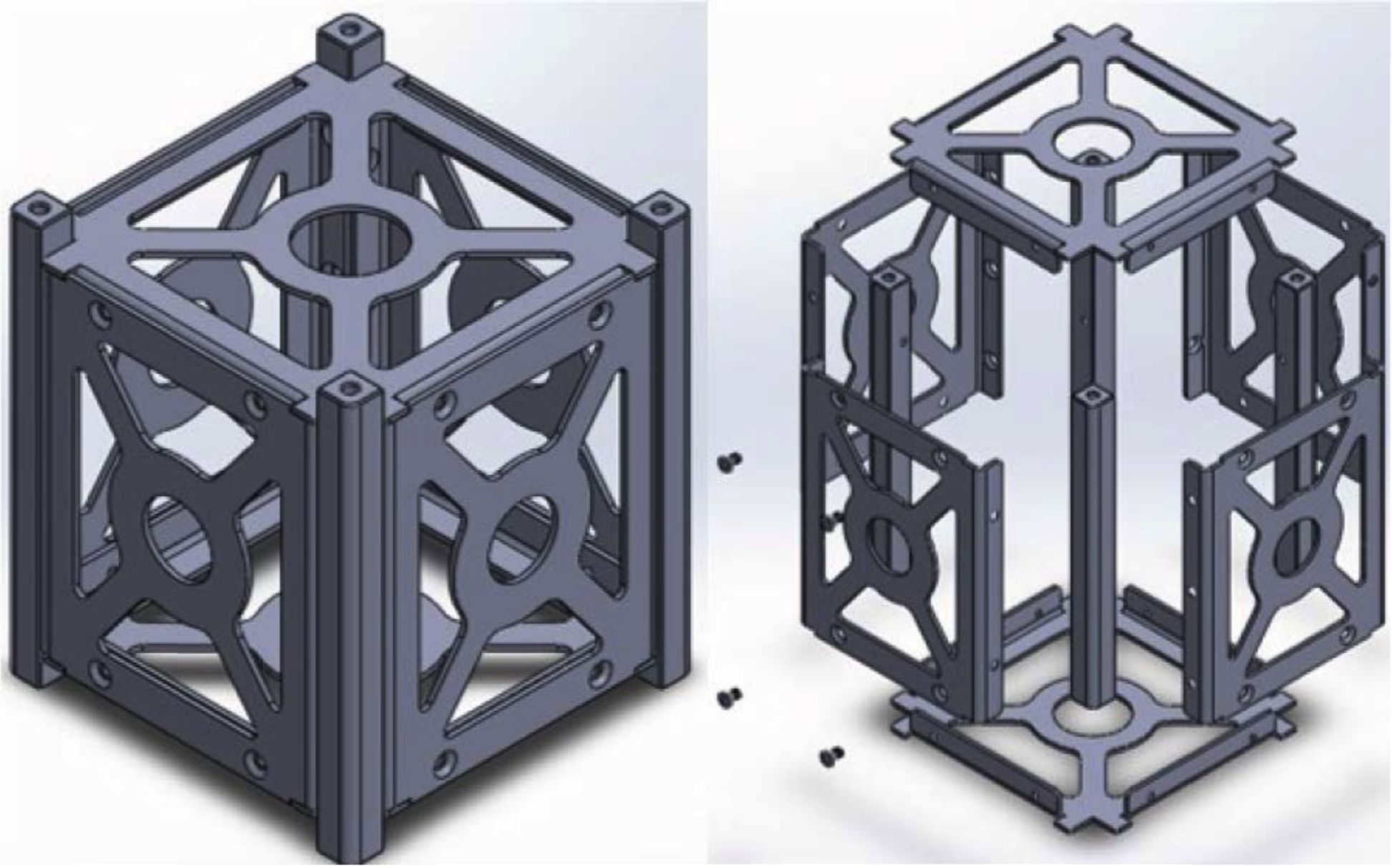
Based on these interactions and the geometric arrangements that together with the modular architecture integrate the nano-satellite, the detailed design generation can be projected referring to both the materials and the components required for the design sequence (Figure 9), this being one of the milestones of the process with respect to the consolidated proposal of the dominant global concept.
Figure 8. System level interactions.
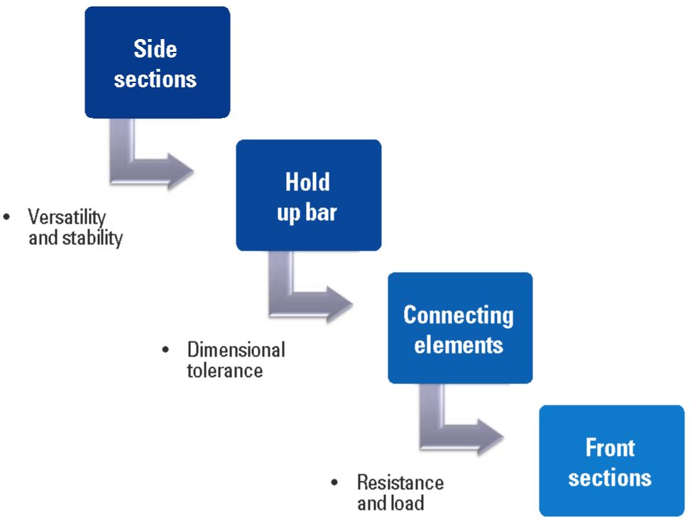
Figure 9. Final graphic model for the CubeSat 1U.
The basis for the process of generating the detailed design is addressed by means of the CubeSat type modular architecture, composed of the basic cubic unit with 100 mm side, called 1U, which is scalable to 2U, 3U, 6U even 12U, as additional units in a single modular structure. This scaling is done depending on the load and the specific requirements of each mission.
Component Selection: The following is the selection of standardized components according to the identification of interactions and operating interfaces of the proposed platform:
a. Connecting elements
b. Structural sheets
c. Divider sections
d. Support profiles
It also stands out that the detailed design must start from the selection of standardized components, where the Poly Picosatellite Orbital Deployer (P-POD) launch vehicle is mainly located, within which the nanosatellite whose structure is being developed is to be housed and for which not only dimensions and materials but also process and deployment standards must be considered, both for launching and for putting into orbit. To do this, the mission design must be clearly defined.
Selection of materials and production techniques: For the right selection of materials and manufacturing processes of custom components of the CubeSat, according to the spatial environment, the following aspects can be mentioned (Sandvik, 2012b):
Definition of spatial restrictions: In addition to the characterization of the materials available for the manufacture of the CubeSat, it is importantto highlight the standardized design of each of the CubeSat configurations about the space restrictions that have been established (Poghosyan & Golkar, 2016), considering the 1U, 2U and 3U configurations, with reference systems such as the physical characteristics and the finishes of the structures.
1) Development and connection of interfaces: Considering the parameters previously related to the standards, both structurally and functionally and material selection. Figure 10 summarizes the functional interfaces of definition, and the development and connection between the subsystems of the product.
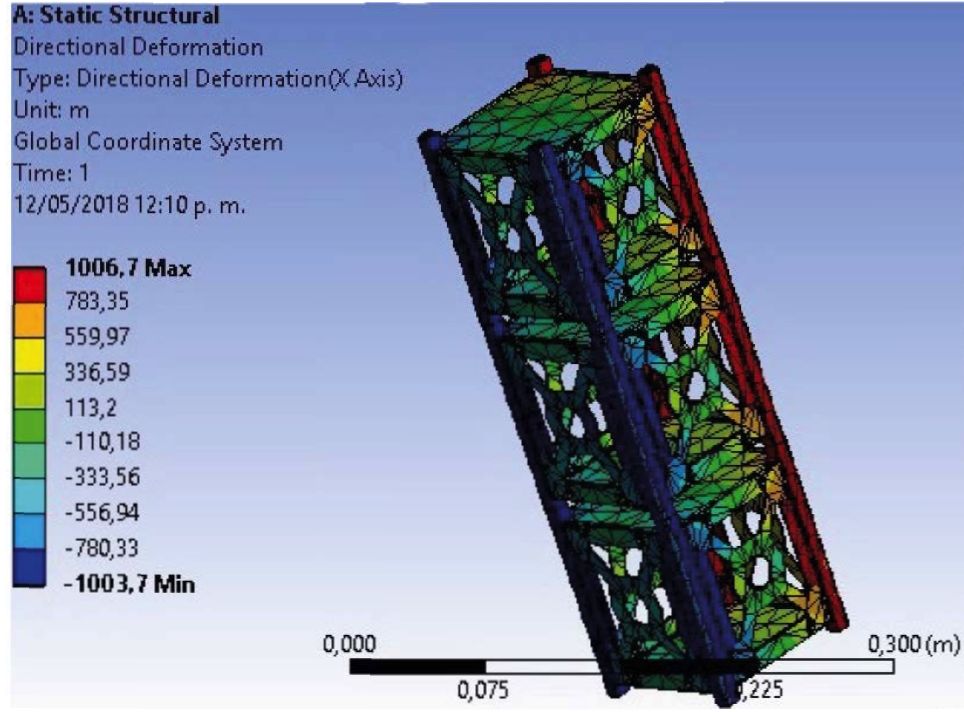
2) Description of calculation and computational tools used: From the geometric and structural definition of the prototype, the static, modal and dynamic analysis of the structure performance scenarios for the CubeSat can be projected. After the simulation of the loads applied to understand their effects (Mooij, 2007), Figure 11 shows the lateral deformations due to the induced stresses; for this restrictions are placed on the bars where the displacement rails are attached to the structure of P-POD (Chin & Puig-Suari, 2008). It can be observed in the results that, despite the generated deformations, the structure remains integrated and the upper and lower sides support the launching forces, without uncoupling the lateral sides of the CubeSat.
On the other hand, Figure 12 shows the simulation of deformation of one of the PCB10 plates that are contained within the CubeSat (Camacho, 2016). There is also an increase in the stresses in the center of the plate where the electronic components of the CubeSat subsystems are located.
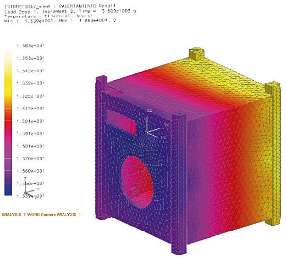
In addition, it is important to study by thermal modeling the effect of temperature changes during the stabilization process of the CubeSat. Figure 13 shows the influence that the light and eclipse phases have on the CubeSat during its positioning in orbit.
After carrying out simulations of loads, vibrations and thermal effects, which study the aspects that most significantly impact a CubeSat, it is observed that both the selection of standards in materials and components comply with the operating requirements of the structure during all phases of operation.
3) Modeling and analysis: As part of the design process, the optimization of the useful volume as a function of the amount of structural material is a fundamental task. To do this, a parametrization of the mathematical model is performed, and a topological optimization of the geometry is used to obtain the final shape of the lateral, upper and lower sides of the structure. The objective volume is defined as the total volume subject to the condition of admissible stress in the structure of the CubeSat, optimizing the payload capacity (Pierlot, 2009). Figure 14 shows one of the simulations used.
The integrity of all the components of the structure is expected from this functional correlation. The right balance must be found between the subfunctions of the platform through the support of the payload, the support of components, the protection, and the isolation of the systems. All these are expressed in geometric terms by means of the design of the lateral, superior and inferiorsides of the CubeSat.
Figure 10. Functional design interfaces.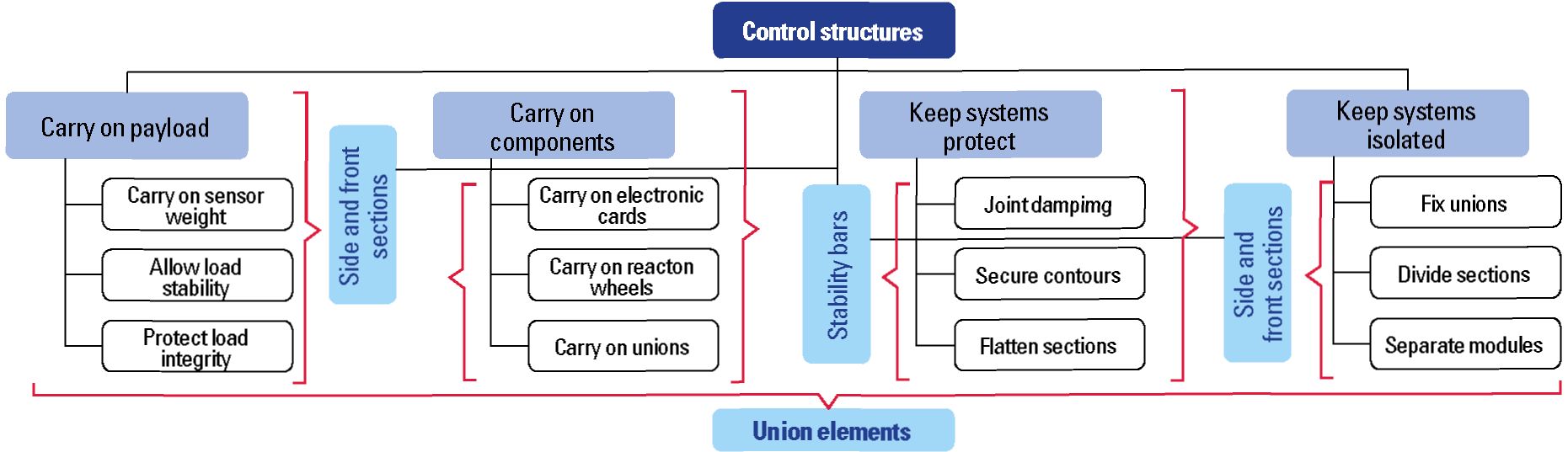
Figure 11. Analysis of displacements on the structure of the CubeSat
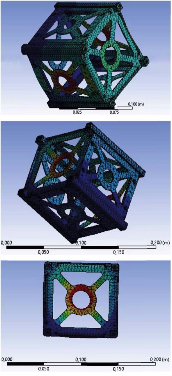
Figure 12. Deformation of the PCB with vibration at 323 Hz Source: Pierlot (2009).
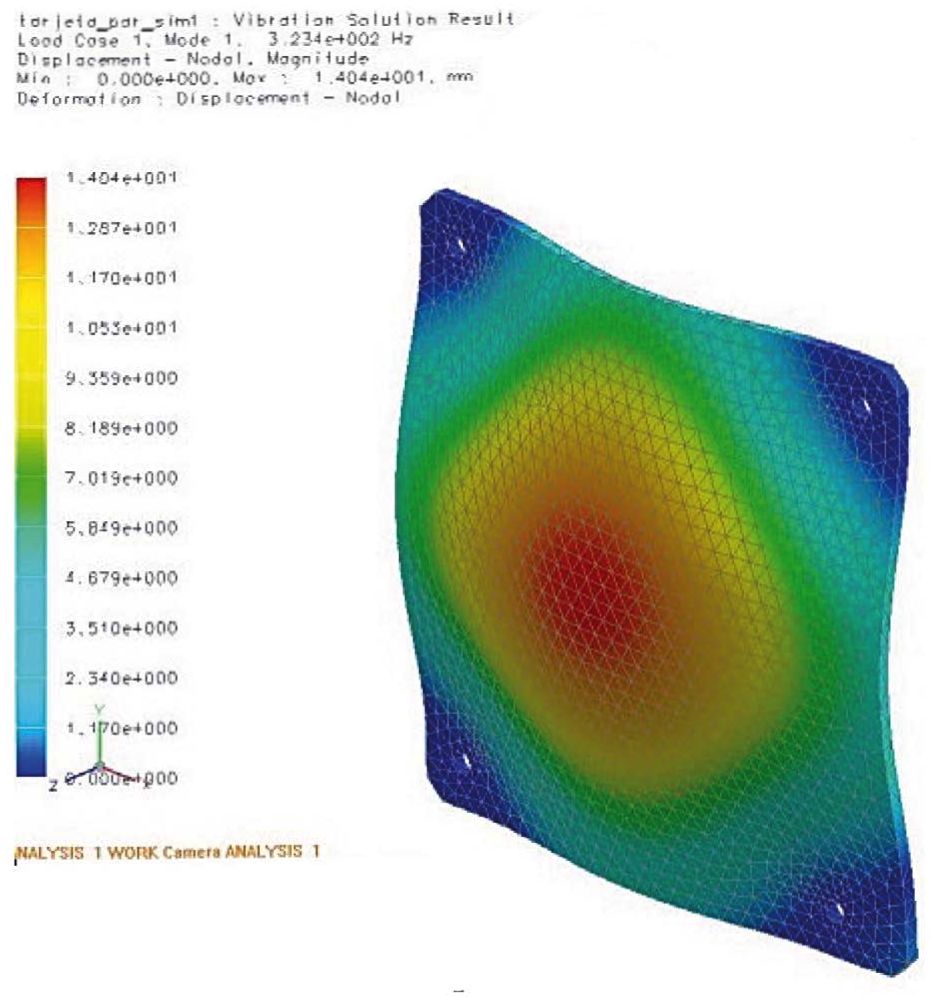
Figure 13. Analysis of the effect of light and eclipse phases.
For the evaluation of the functions and performance of the product, the prescriptive model of the planning phase is taken as reference with the different steps of the process, which are of use and application in nanosatellite systems. About the different requirements of the customer, Table 5 shows the basic design criteria, considering the defined levels of importance, to carry out the respective evaluation of the selected detailed design.
Table 5. Evaluation of compliance with customer requirements.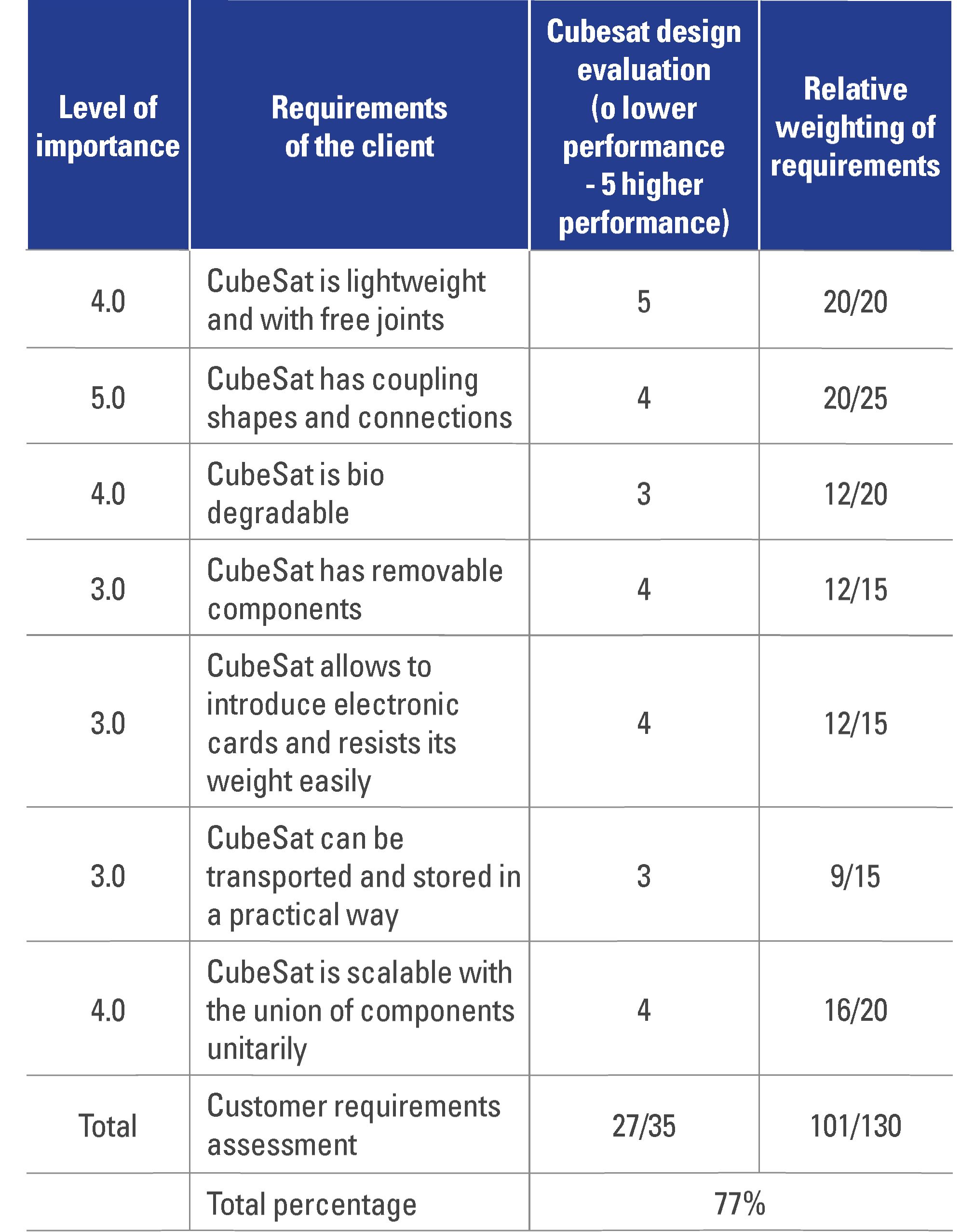
Tabla 6. Shows the evaluation of compliance with the engineering specifications for the selected detail design.
Table 6. Evaluation of engineering specifications.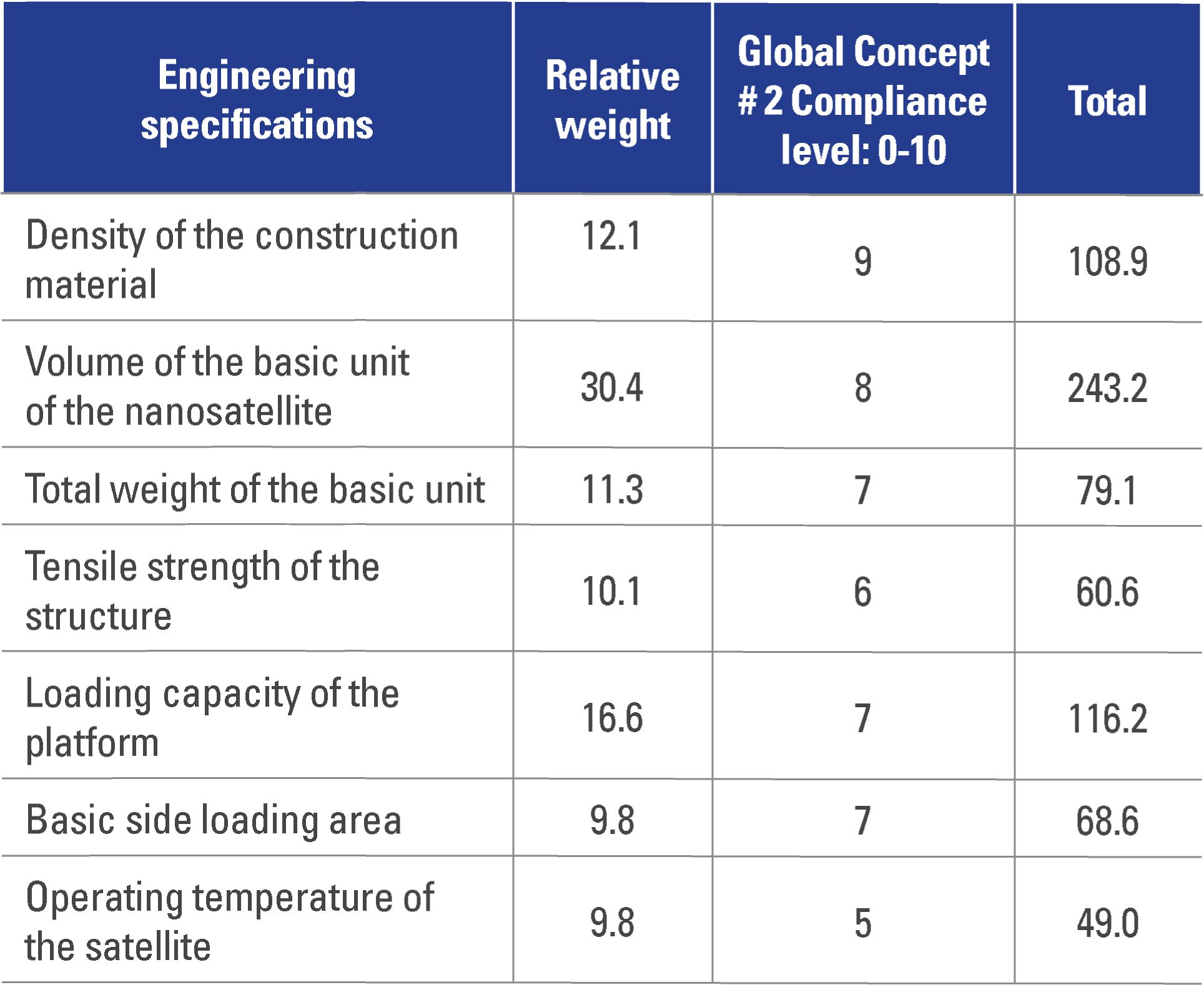
The design oriented to the manufacturability, the assemblability, and the analysis of costs retakes the analysis and redefinition of each one of the components, along with the constructive processes required to obtain the CubeSat at a competitive cost. For this, not only the inputs and outputs of a manufacturing system are considered, but also the materials and products involved in the production activities of the CubeSat.
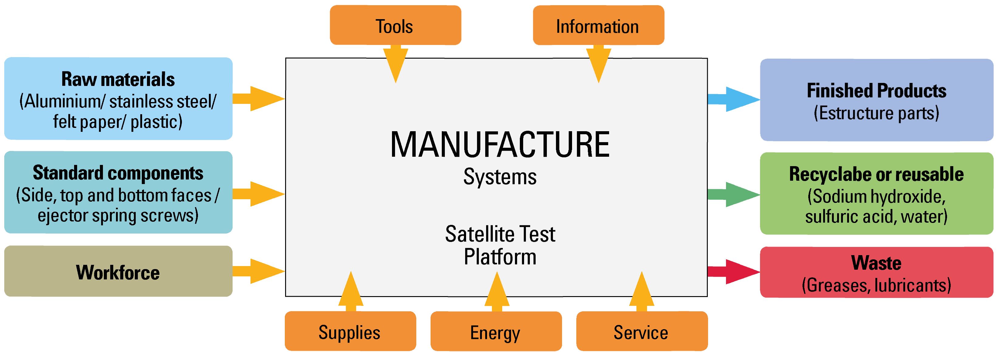
1) Design oriented to manufacturing: Manufacturability is approached from the analysis of the manufacturing system necessary to produce CubeSat. Figure 15 shows a diagram detailing the inputs and outputs necessary to guarantee the manufacture of the product in question. The inputs consist of the raw materials, such as the basic construction materials of the platform (Delgado, 2016), the standardized components, the estimate of the labor, supplies, energy, services, tooling, and necessary information for each one of the required processes. On the other hand, the outputs of the system are composed of finished products, waste materials, recyclable and reusable parts.
The manufacturing processes of the CubeSat type structure considers the following work groups and process parameters:
Sheet cutting processes:
Machining processes:
Bending process:
Milling process:
Surface coating process:
The cost model is based on the calculation of the production cost of a unit of product, which is determined by means of the expression (1).
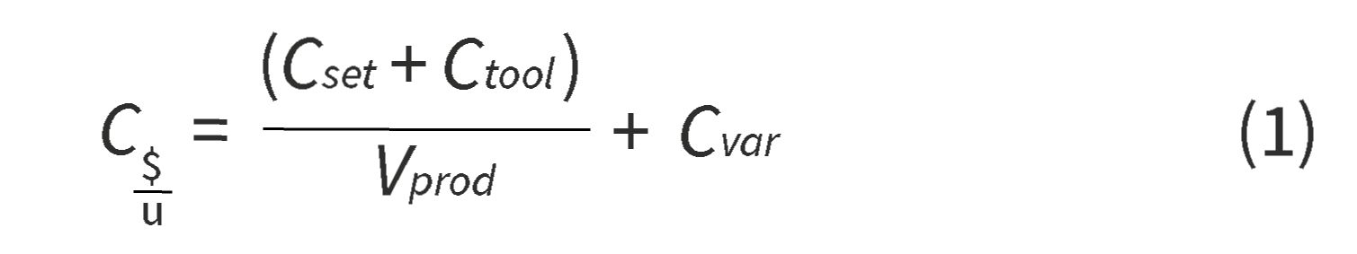
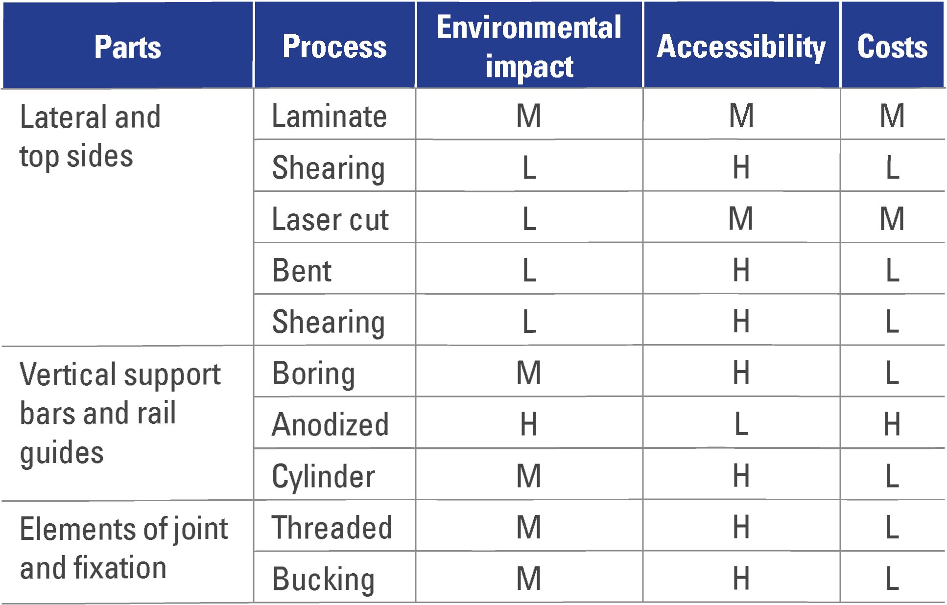
where C is the total cost of production of a unit of product, Cset is the cost of preparation, Ctool is the cost of tooling and other non-recurring costs, Vprod is the volume of production and Cvar the variable costs to produce a product unit. According to the processes formulated in Table 7, the evaluation of manufacturability is related to each of the pieces of CubeSat, qualifying the level of impact, accessibility, and estimated costs (Gallegos, 2009).
2) Design oriented to assemblability: Based on the disposition of the different parts of the structure, the characteristics and qualifications of the assemblability performance of the design are evaluated. For this, the number of parts and fasteners, assembly sequences, coupling trajectories, and accessibility to the different interfaces are considered. From this, 54 reference points are obtained as evaluation parameters and improvement criteria for the design of the components, where the general scheme, the recovery of parts, and the handling and joint of these are evaluated. The cost model for the task of assembling the product is defined with the help of expression (2) (Boothroyd, 2005).

Where Co is the cost of assembly, is the hourly rate of assembly, CH in the equation tman is the time to take and manipulate the components and finally is the time to attach and fix the components.
Figure 15. Scheme of the manufacturing system required to produce CubeSat.
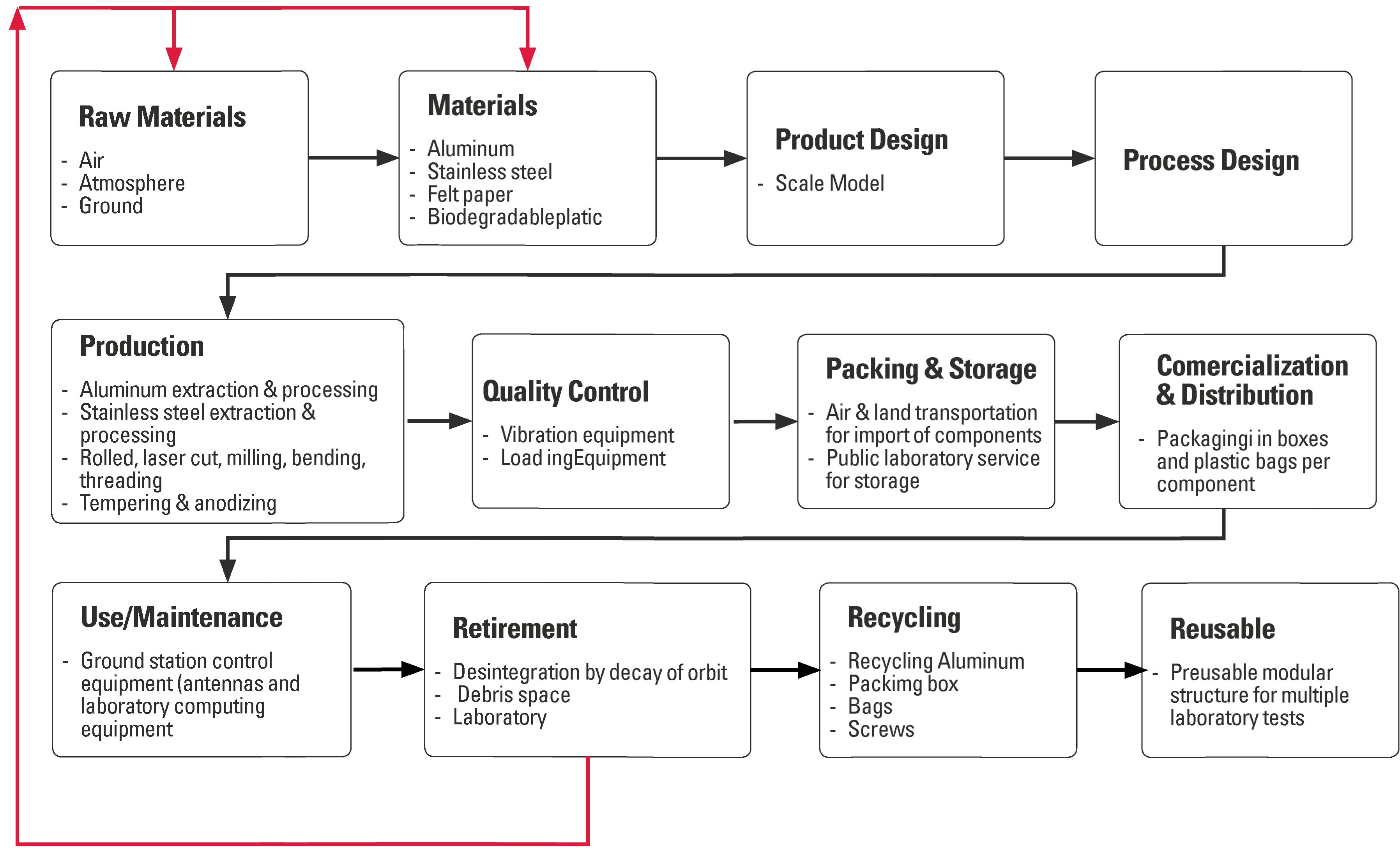
For the analysis of the environmental impact, the life cycle of the satellite test platform is defined, with which the different aspects that generate a certain impact are identified and related to the intensity of use of the raw materials, standardized components, process of production, quality control, packaging, storage, marketing and distribution, use by the customer, maintenance and repair, product recall, recycling and reuse (EFIU/UPV, 2017). Figure 16 shows a simplified diagram of the life cycle phases forthe CubeSat.
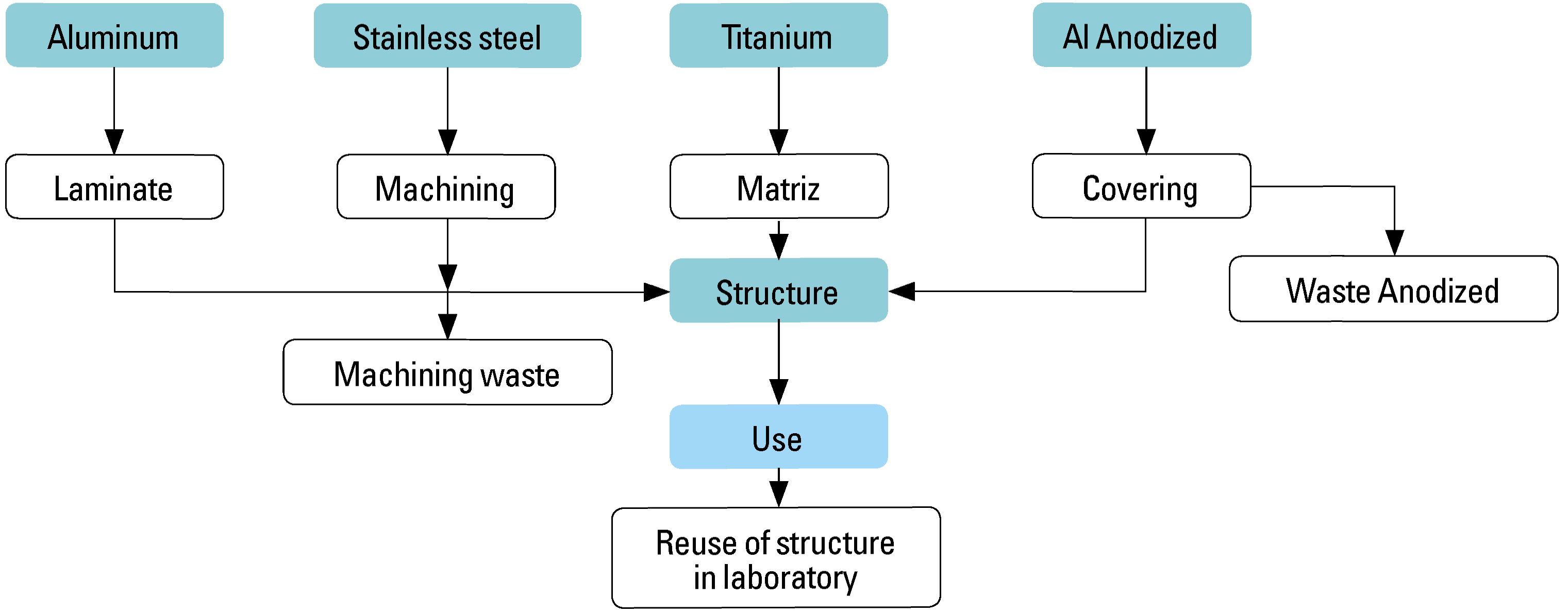
For this activity, the CubeSat life cycle process tree is developed (Figure 17) based on the different basic composition materials of the structure, processes, uses and final disposal. Forthis product, there is a multipurpose disposition in the laboratory. The above as a result of its nature, destined to the simulation of systems on land and the modeling of multi-agent control systems with on-board equipment.
Based on the life cycle and the product process tree, improvement strategies aimed at achieving a sustainable design are implemented. Forthis purpose, the concepts of each strategy, their respective scales and comparison with the reference model of the market and the designed product are used. As strong aspects of the generated product, we can mention the significant reduction in the use of materials and the decrease of the environmental impact during use, typical of a reusable platform. The eco-efficiency index of the proposed design is an important indicator to characterize the efficiency of the product in terms of the value it produces and how much it negatively impacts the environment throughout its life cycle (Louzguine et al, 2000). The eco-efficiency index is calculated according to the equation (3).

Where Ieco is the index of eco-efficiency, V the value of the product, and Ellc is the environmental impact throughout the life cycle of the product. As a value of the product, the estimated net profit is taken accord-ingto the sale price that the potential customerwould be willing to pay and the unit production cost that has been projected. On the other hand, to determine the environmental impact during the life cycle, it is necessary to determine the individual values of each of the processes involved in the manufacture, distribution. final use of the platform, and removal of the product at the end of its useful life. Here we take as a starting point, for example, the extraction of bauxite ore and the production of aluminum as the main material of several of the CubeSat components.
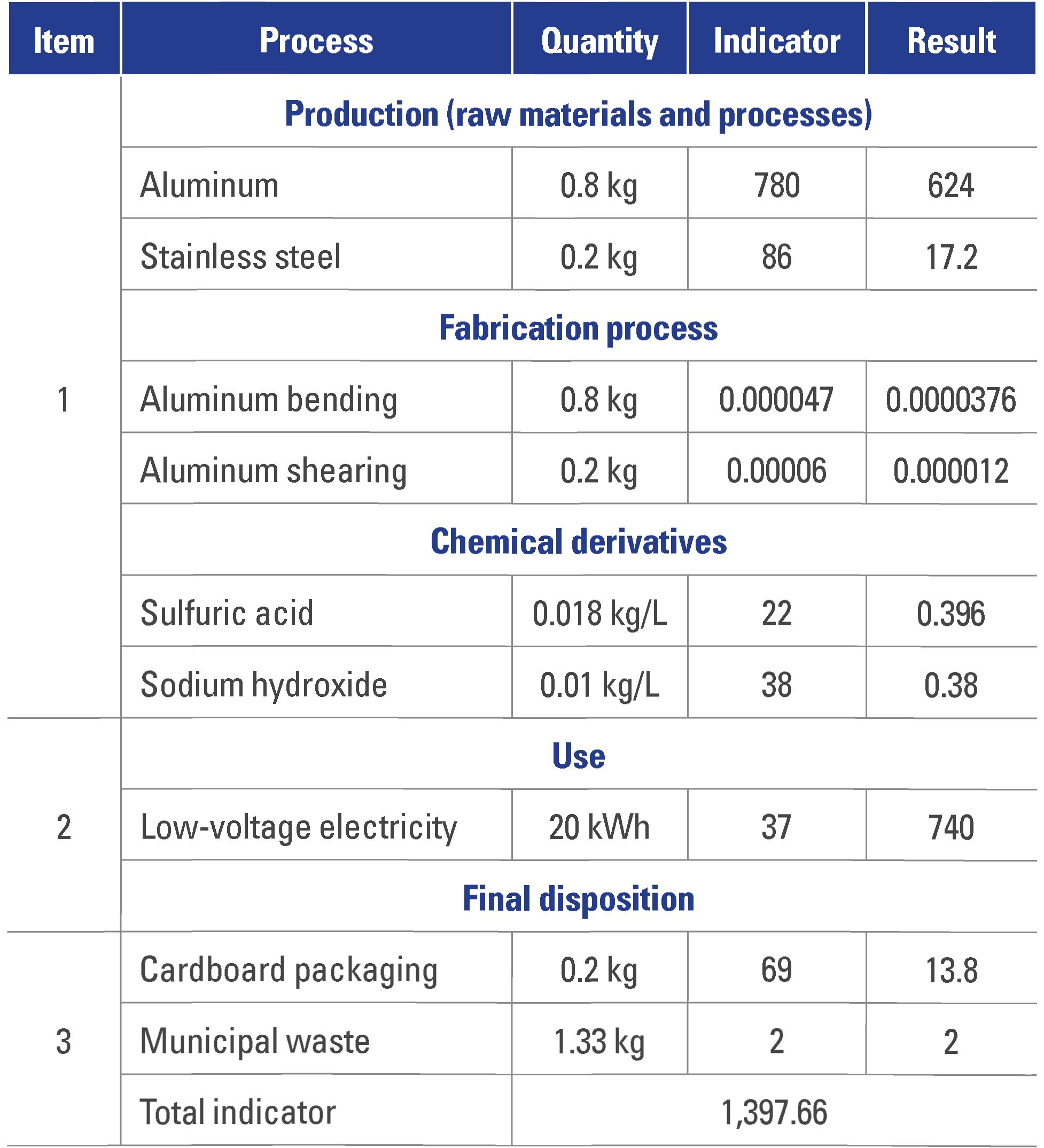
About the different processes previously described, the environmental impact assessment for CubeSat is presented in Table 8.
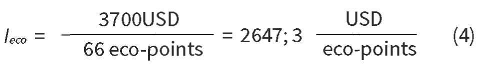
Returning the index of ecoefficiency with the value of utility of the estimated product of USD 3,700, due to the quantification of total costs of investment in the platform and the value of environmental impact totalized during the life cycle, the CubeSat modularstructure has an eco-efficiency index as calculated in equation (4).
Design oriented to reliability: The following verification aspects and test specifications are verified for the approval of the CubeSat structure at the time of sched-ulingthe launch:
a. Test of structural loads: support acceleration in each axis and in both directions.
b. Random vibration test: support random vibration environment.
c. Test of sinusoidal vibrations: support sinusoidal vibrations environment.
d. Spatial thermal cycle test: withstand thermal cycles without presenting fatigue failure.
Taking the categories of tests performed on the CubeSat structure for its operation, the vibration test was selected as a reference for the analysis of the reliability of the design. For this, the test parameters for the design of experiments that appear in (Kuehl, 2001) are taken, which is done by the computational simulation method.
The central purpose of the experimental design is to determine the fault elements subject to structural vibration loads, such as modeling the process of placing a CubeSat into orbit according to the standards by the European Cooperation for Space Standardization (ECSS). The hypothesis to be tested is the following: the structural supports and joining elements of the modular platform remain coupled and fixed under the conditions of the vibration test. To answer this, the following independent factors and experimental response are established:
Experimental factors:
Response variables to be measured:
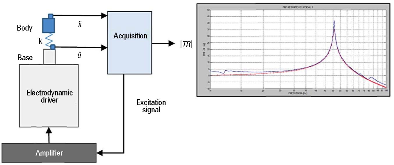
Figure 18 shows the arrangement of the elements used to carry out the experiment. The main components of the experimental assembly are:
At the end of the acceptance of the proposed hypothesis, based on the simulations, the rethinking and refinement of the physical model and the product prototype take place. Then a revaluation of the client’s requirements and engineering specifications is performed.
Design oriented to security: This activity considers the following aspects of safety within the concept of structural design of the test platform, which present the conditions under which risk factors could occur in the product:
a. Design of components without dimensional tolerances
b. Materials not resistant to extreme temperatures
c. Failed structural support tests
d. No use of standards for the structure and components on board
e. Non-modular or scalable design
f. Absence of quality controls (dimensional tolerance control, mechanical properties control of materials, etc.)
g. No availability of a component assembly manual
Finally, the failure mode and effect analysis (FMEA) is developed, whose fault evaluation matrix is shown in Table 9. This identifies the potential potential failures of CubeSat, together with the evaluation of the level of severity, estimated frequency occurrence, and ease of detection. The product of these three variables allows the calculation of the priority risk number (PRN). The latter establishes an order of priority for potential failures and facilitates the drawing up of an effective action plan, necessary to minimize or eliminate the risk of the product developed.
Based on the identification of the potential mode of failure, its effects, and the PRN, the risk management and minimization actions are projected (Tsarev, 2013). In the case of CubeSat, the support function of the components resulted in a PRN of 270 points. Fortunately, for this case, because it is a test structure on the ground, it would not be exposed to the thermal effects or extreme loads to which these platforms are exposed.
Finally, a strategy to improve industrial design was implemented. The structure is revised in terms of including the following design features: defined and scalable geometries for the coupling between sides and support bars; geometric interstices for the identification and visualization of internal components, beveled sections for easy manipulation and positioning between sides; smooth surfaces for the anti-adhesion of material external to the structure; and holes symmetrically distributed forthe union of components and an easy location of elements within the structure.
Table 9. Matrix of modal analysis of failures and their effects.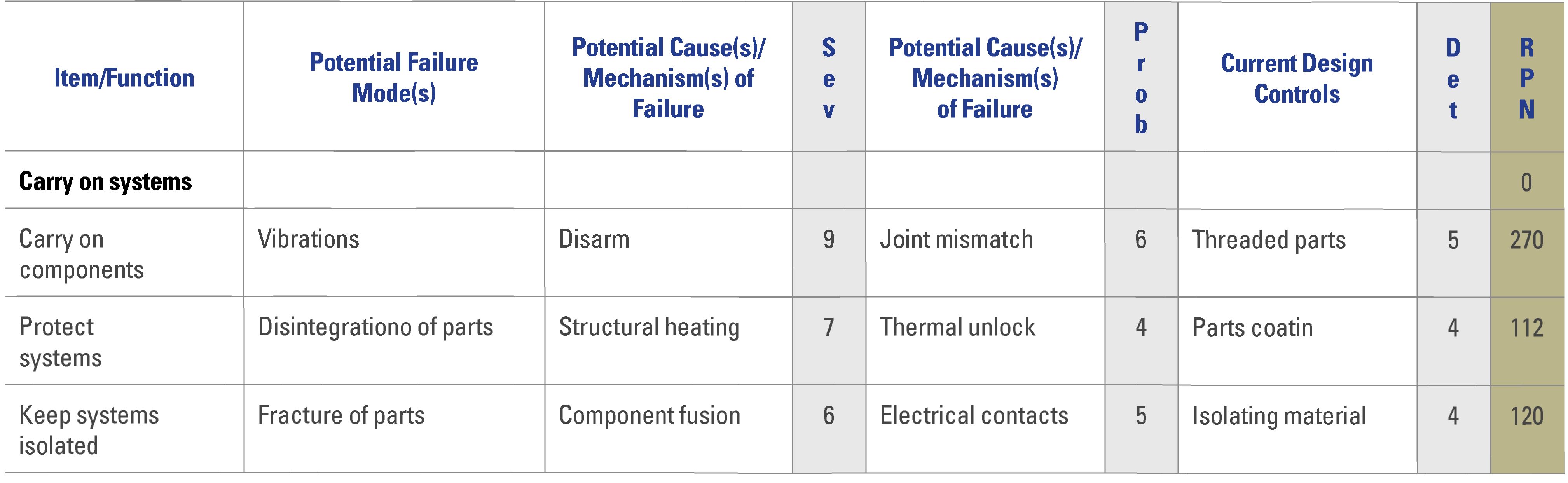
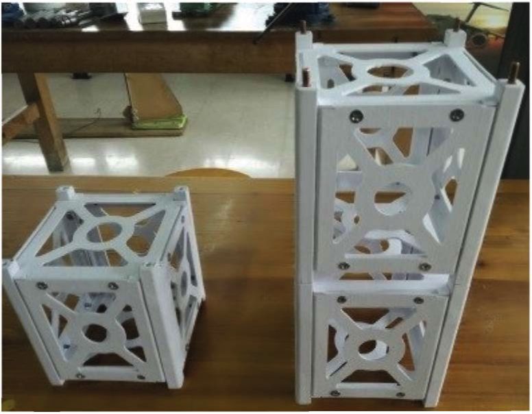
To apply the design process developed, the construction of the model is carried out using the prototyping technique by 3D printing —the first with cellulosic construction material and the second in polymeric material type Acrylonitrile Butadiene Styrene (ABS)— with the object of proposing two alternatives for the use of modular structures in the laboratory. The above, under the premise of dimensional tolerance assessment and selection of the best sustainable performance option, both for its environmental impact and for its complete design, manufacturing and end use condition, with subsystems on board forspecific tests in each material.
The manufacturing processes used to manufacture the prototypes are described next. First, developed 3D models are converted to an .stl extension, which is suitable for prototyping. Subsequently, the model parts are placed inside the work trays and the configuration of the polymer injector step is executed in the case of the ABS and the cutting blade in the case of paper printing, as well as the application of the additive for the adhesion of each one of the sheets of paper. Then, the determination of the volume of material for the model and the support material for the two printing cases is made, from where the estimation and time projection for the printing process is made, according to the number of trays configured by the number of parts required. Finally, the demolding is carried out, which for the case of paper is expensive due to the separation of the model from the layers adhered to the paper block. The use of polymer requires acids for the removal of support material, which negatively impacts the environment and decreases the rate of eco-effi-ciency of this product. After the demolding process, the finish and integrity of each of the parts is verified, and the final model is assembled and tuned for each of the manufacturing methods used.
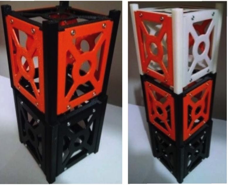
Figure 19 shows the models constructed with cellulose, both in the 1U and 3U configuration, respectively. Figure 20 shows the models built with ABS, both in the 2U and 3U configurations, respectively. All are defined as a structural subsystem according to the CubeSat standard. On these structures it is possible to assemble the CubeSat work subsystems: thermal subsystem, subsystem of control and attitude determination (ADCS), electrical power subsystem (EPS), communications subsystem, and subsystem of commands and data. They can be assembled in the structure and put to the test (Araya, 2014), for evaluation of space technologies, in laboratories workbenches, where variables of analysis in aerospace development projects are specified.
Final ABS prototypes allow us to recreate the classic CubeSat structure varying the materials, sizes, volume, and manufacturing.
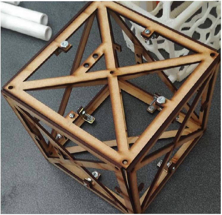
The prototype in wood (Figure 21) was made with agglomerated wood medium density fibreboard (MDF) of 3 mm thickness, and was manufactured with laser cut.
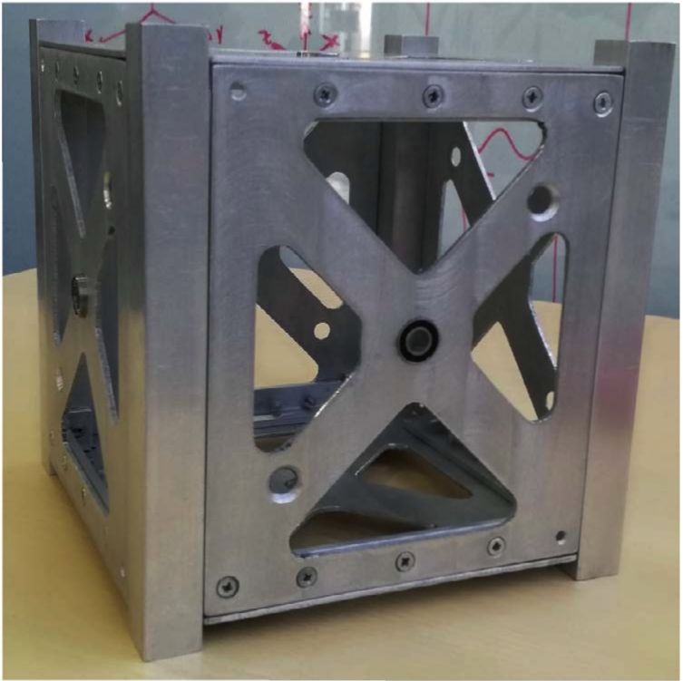
The prototype in aluminium of the Figure 22 was elaborated with aluminium-60601 with 2 mm of thickness. The complete design and manufacturing is available in the work by Cortes-García et al. (2019).
The results of the design and construction process of the test platforms from different materials pose several challenges not only to the manufacturing processes but to the achievement of raw materials and assembly processes, such is the case of the evaluation of physical properties and with the machining and associated tools, for final disposal as modules of the test system.
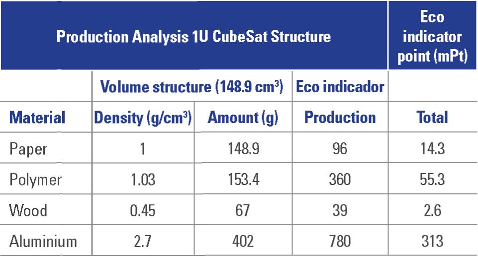
The analysis of the eco-indicator against the production of a material for the manufacture of the 1U structure (Louzguine et al., (2000) (Table 10) offers an overview of the impact that the current production of these structures generates with the different exposed materials. However the analysis should be further expanded to the complete processes of the life cycle of the test platforms. In this sense, it is necessary to include aspects of reuse, recycling or disposal, as well as aspects of maintenance and frequency of use in a laboratory, to assess the effect or drastic reduction of their life useful. Just as the life cycle conditions of the structure give a guide for its production, so do the processes of component instalation, assembly, and the effects of the tests themselves, which are precisely aspects to consider in the final design process of the test structures, with which various constructive options are given for their use, depending on the type of test and the efforts to which the platforms will be subjected in the laboratories.
According to the CubeSat Design Standard (CDS) (Carnahan, 2014), a test performance is needed to accomplish the Launch Provider’s requirements. Generally, CubeSats are coupled into P-POD,and after the launch procedure they are deployed into space; reason why those tests must be performed with this coupling POD. At the very minimum, all CubeSats will undergo the following tests:
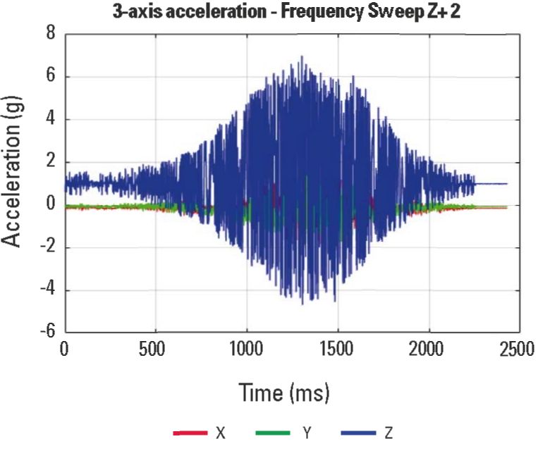
According to the different tests these structures must undergo, only the vibration test for one of the platforms built is taken as an application example, taking into account that other projects for the design of benches are being developed at the same time; test that in subsequent phases of the present project will be integrated into the developments. The National University of Colombia has a Vibration test bed located at the Electrical Labortories, where the Random Vibration Testing can be performed (figures 23 and 24). This test bench can performance vibrations up to 100 Hz and 5 g of acceleration, as shown in Figure 25.
However a P-POD is needed to coupled the 3D-printed CubeSats and perform according to launch providers requirements.
Figure 23. Non-standard CubeSat coupled at Vibration test bench.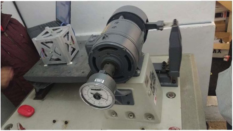

The application of the sustainable product design process allowed the presentation of the integrated use of modular satellite platforms in accordance with the CubeSat Standard. With this, it is possible to implement simulation exercises of the different types of satellite subsystems on a small scale for tests at the laboratory level.
A set of design techniques was applied forthe selection of the dominant global concept and the correct development of the detailed design required to present an alternative model of experimental structure. This work motivates and promotes work on space issues, thus allowing the development of the aerospace sector in the country and the search for tools to apply control techniques and design strategies on the different subsystems on board the structure.
The final prototype CubeSat covers the need of different centers and research groups, as well as companies in the sector, to implement prototypes and devices on which research resources related to modular platforms can be applied, either to test existing systems technologies of control or to model behaviors of new developments that placed in orbit can offer better performances than those currently obtained by small-scale satellite systems.
For emerging economies these platforms allow a closer and more favorable approach for the adaptation and appropriation of satellite technologies, to the point of contributing in the medium term to the design of space missions or programs with which academia, industry and the state join efforts to have direct control, and not outsourced, of the aerospace services in the national territory.
Implement and improve design techniques, as well as having adequate laboratories for full compliance with the CDS quality standard.
In the same way, acquire adequate instrumentation forthe study of the subsystems present in a satellite, as well as the design and development of modular CubeSat platforms for the promotion of educational and productive spaces where skills and work techniques are developed in classrooms, laboratories and research facilities, which make it possible to analyze the behavior of variables and propose new designs and processes fortraining in space.
Lastly, aim at the design and creation of satellites that can be put into orbit with functional missions.
5 Teorija Rezbenija Izobretatelskib Zadach (Inventive Problem Solving Technique).
6 CG1. Sheets, rivets, profiles.
7 CG2. Bars, screws, sections.
9 CG4. Pivot, blades, screws, stops.
Alvarez, J., & Walls, B. (2016). Constellations, clusters, and communication technology: Expanding small satellite access to space. 2016 IEEE Aerospace Conference. Big Sky. https://doi.Org/10.0.4.85/AERO.2016.7500896
Ampatzoglou, A., & Kostopoulos, V. (2018). Design, analysis, optimization, manufacturing, and testing of a 2U CubeSat. International Journal of Aerospace Engineering, 2018, 1-15. https://doi.org/10.1155/2018/9724263
Antunes, S. (2012). Surviving orbit the DlY way. O’Reilly Media.
Araya, F. (2014). Modificación de la estructura principal de un nanosatélite. ESSS Conference & ansys Users Meeting, ESSS & ANSYS Users.
Báez, A. A., & Rodríguez, O. A. (2010). Diseño de los sistemas estructural, de alimentación de energía solar y construcción de prototipo estructural de un pico satélite para el C.I.E. de la ESPE. [Engineer thesis, Universidad de las Fuerzas Armadas ESPE]. Repositorio Institucional de la Universidad de las Fuerzas Armadas ESPE.
Boothroyd, G. (2005). Assembly automation and product design. Taylor & Francis.
Bouwmeester, J., & Guo, J. (2010). Survey of worldwide pico-and nanosatellite missions, distributions and subsystem technology. Acta Astronaut, 67(1-8), 854-862.
California Polytechnic State University [CalPoly]. (2009). Cubesat design specification. Calif. Polytech. State, 8651,22.
Camacho, F. (2016). Diseño óptimo de estructuras satelitales [PhD thesis, Universidad Nacional Autónoma de México]. Repositorio digital de la Facultad de Ingeniería, UNAM.
Carnahan, J. (2014). Cubesat design specification. Calif. Polytech. State, (SLO 4).
Cortes-García, E. D., Acuña-Mateus D. F., & Pachón-Pinilla, J. A. (2019). Diseño, construcción y experimentación de un satélite de pequeña escala. Facultad de Ingeniería, Universidad Nacional de Colombia.
Díaz-González, F. A., Quintero-Torres, S. V., Triana-Correa, J. S., Morón-Hernández, D. C. (2014). Aproximación a los sistemas de percepción remota en satélites pequeños. Fondo de Publicaciones Universidad Sergio Arboleda.
Gallegos, R. A. (2009). Diseño e ingeniería asociada a lo estructura de un Picosatélite [Engineer thesis, Universidad Autónoma de Nuevo León]. Repositorio digital de la Facultad de Ingeniería, UNAM.
Gavrilovich I., Krut, S., Gouttefarde, Pierrot, F., & Dusseau, L. (2014). Test bench for nanosatellite attitude determination and control system ground tests. 4S: Small Satellites Systems and Services Symposium. National Centre for Space Studies, France.
González-Silva, M. A., & Paredes-Mera, F. J. (2010). Diseño y construcción de un banco de pruebas de vibraciones para la optimización del picosatelite hexasat del centro de investigación espacial, CIE [Engineer thesis, Universidad de las Fuerzas Armadas espe]. Repositorio Institucional de la Universidad de las Fuerzas Armadas ESPE.
Herrera-Arroyave, J. E. (2015). Diseño estructural de un sistema CubeSat con recubrimiento de barrera [Master’s thesis, Universidad Autónoma de Nuevo León]. Repositorio Académico Digital UANL.
Herrera-Arroyave, J. E., Santillán-Gutiérrez, S. D., Zambrano-Robledo, P. C., & Ferrer-Pérez, J. A. (2015). Proceso de diseño de una estructura nanosatelital CubeSat. XI Congreso Internacional sobre Innovación y Desarrollo Tecnológico. ieee Sección Morelos.
Herrera, J., Ledezma-Ramírez, D., Flernández, G., Ferrer, J., Zambrano, P., & Bermúdez, B. (2015). Diseño estructural de un sistema CubeSat con recubrimiento de barrera térmica. VII Congreso Internacional de Ingeniería Mecánica. Facultad de Ingeniería, Universidad Nacional de Colombia.
Louzguine, D. V., Inoue, A., Saito, M., & Waseda, Y. (2000). Eco-indicator99 Manual for Designers. Technical Report, Ministry of Flousing, Spatial Planning and the Environment, European Union.
Maropoulos, P. G., & Ceglarek, D. (2010). Design verification and validation in product lifecycle. CIRP Annals-Manu-facturing Technology, 59(2), 740-759.
Medina, D. P. (2018). Diseño y manufactura de la estructura de un CubeSat 2U [PhD thesis, Universidad Nacional Autónoma de México]. Repositorio digital de la Facultad de Ingeniería, UNAM.
Meissner, D. (2019). A three degrees of freedom test-bed for nanosatellite and cubesat attitude dynamics, determination, and control [B.S. Aerospace Engineering thesis, United States Naval Academy]. Institutional Archive of the Naval Postgraduate School, United States of America.
Mier-Flicks, F. (2017). Space-craft charging and attitude control characterization of electrospray thrusters on a magnetically levitated testbed [PhD thesis, Massachusetts Institute of Technology], mit Libraries.
Mooij, E., & Ellenbroek, M. FI. M. (2007). Multi-functional guidance, navigation, and control simulation environment. AIAAA Modeling and Simulation Technologies Conference and Exhibit. American Institute of Aeronautics and Astronautics.
Osdol, T. C., Dorsey, C., Fledlund, J., Floye, T., Jacobs, 0., Klar-reich-Giglio, K., Martin, E., Ruiz, M., Schlesselmann, M.,& Singh, Z. (2013). Design, fabrication, and analysis of a 3U Cubesat platform [Engineer thesis, Santa Clara University]. Santa Clara University Scholar Commons.
Pierlot, G. (2009). Flight system configuration and structural analysis [Master’s theis, University of Liege]. Institutional Repository of the University of Liege.
Poghosyan, A., & Golkar, A. (2016). Progress in aerospace sciences cubesat evolution: Analyzing cubesat capabilities for conducting science missions. Prog. Aerosp. Sci., (September), 1-25.
Radhakrishnan, R., Edmonson, W. W., Afghah, F., Rodriguez-Osorio, R. M., Pinto, F., & Burleigh, C. S. (2016). Survey of inter-satellite communication for small satellite systems: Physical layer to network layer view, IEEE Communications Surveys & Tutorials, 18(4), 2442-2473. https://doi.org/10.1109/COMST.2016.2564990
Rodríguez, G. W. (2017). Diseño n: gestión tecnológica para el diseño de proyectos de ingeniería. Escuela de Postgrados de la Fuerza Aérea Colombiana, https://doi.org/10.18667/9789589940693
Romero, D., & Rodríguez, H. (2005). Diseño y construcción de un nanosatélite. Technical report. Escuela Superior de Ingeniería Mecánica y Eléctrica, Mexico.
Ulrich, K. T., & Eppinger, S. D. (2015). Product design and development McGraw-Hill Education.
Sandvik, K. (2012). Development of Composite and Polymer Material CubeSat Structure with focus on Materials. Technical report, Norwegian University of Science and Technology.
Tirado, G., & Rodríguez, G. W. (2016). Modelo pi. Modelo para la producción intelectual, una propuesta para las instituciones de educación superior. Escuela de Postgrados de la Fuerza Aérea Colombiana, https://doi.org/10.18667/9789589940679
Tsarev (2013). Smart solutions: Multi-agent technology for real-time enterprise resource management, IEEE/acis 12th International Conference on Computer and Information Science (ICIS). https://doi.org/10.1109/ICIS.2013.6607827
Ullman, D. G. (2010). The mechanical design process. McGraw-Hill.
Universidad del Pais Vasco [ehu/upv]. (2017). Informe de vigilancia y competitividad ambiental en el sector de la máquina herramienta Nerea Sópelana. Basque Ecode-sign Center, ehu/upv.